
Computer-implemented method for reducing crosstalk in a computer-based audiometer

a computer-based audiometer and crosstalk technology, applied in the field of computer-implemented methods for reducing crosstalk in computer-based audiometers, to achieve the effect of reducing undesired crosstalk signals

Active Publication Date: 2020-05-19
SHOEBOX LTD
View PDF13 Cites 0 Cited by
  • Summary
  • Abstract
  • Description
  • Claims
  • Application Information

AI Technical Summary

Benefits of technology

The present invention provides a computer and a computer-based audiometer that has channels that are not fully isolated. These channels perform a computer-implemented method to reduce unwanted signals that interfere with the computer or the audiometer. This improves the accuracy and reliability of the information obtained from the computer or the audiometer.

Problems solved by technology

For computer-based audiometers built on a generic platform, such as a PC, Mac, iOS or Android device however, the hardware has typically not been designed to minimize crosstalk to within ANSI standards, which leads to the need for the present software-based crosstalk compensation technique.

Method used


Image

  • Computer-implemented method for reducing crosstalk in a computer-based audiometer
  • Computer-implemented method for reducing crosstalk in a computer-based audiometer
  • Computer-implemented method for reducing crosstalk in a computer-based audiometer

Examples


Embodiment Construction

[0027]The following description is presented to enable a person skilled in the art to make and use the invention, and is provided in the context of a particular application and its requirements. Various modifications to the disclosed embodiments will be readily apparent to those skilled in the art, and the general principles defined herein may be applied to other embodiments and applications without departing from the scope of the invention. Thus, the present invention is not intended to be limited to the embodiments disclosed, but is to be accorded the widest scope consistent with the principles and features disclosed herein.

[0028]A crosstalk compensation system and method is disclosed for use in a computer-based audiometer. Crosstalk that couples between channels is reduced through use of a software module which modifies digital samples being sent to a digital-to-analog converter. The following definitions will assist in understanding the nature of the invention as described herei...


PUM


Abstract

A computer-implemented method for reducing undesired crosstalk signals on an inactive channel of a device comprising the steps of: (i) determining system volume levels required to achieve a range of desired audio output attenuation levels on an active channel of the device; (ii) determining a crosstalk compensation signal comprising a signal amplitude and associated phase shift required to reduce undesired crosstalk on the inactive channel of the device for each desired audio output attention level in the range of desired audio output attenuation levels; and (iii) generating a desired audio output attenuation level on the active channel of the device by generating a signal at the determined system volume level required to achieve said desired audio output attenuation level, and generating a contemporaneous crosstalk compensation signal on the inactive channel of the device by generating a signal at the determined signal amplitude and associated phase shift required to reduce the undesired crosstalk on the inactive channel.

Description

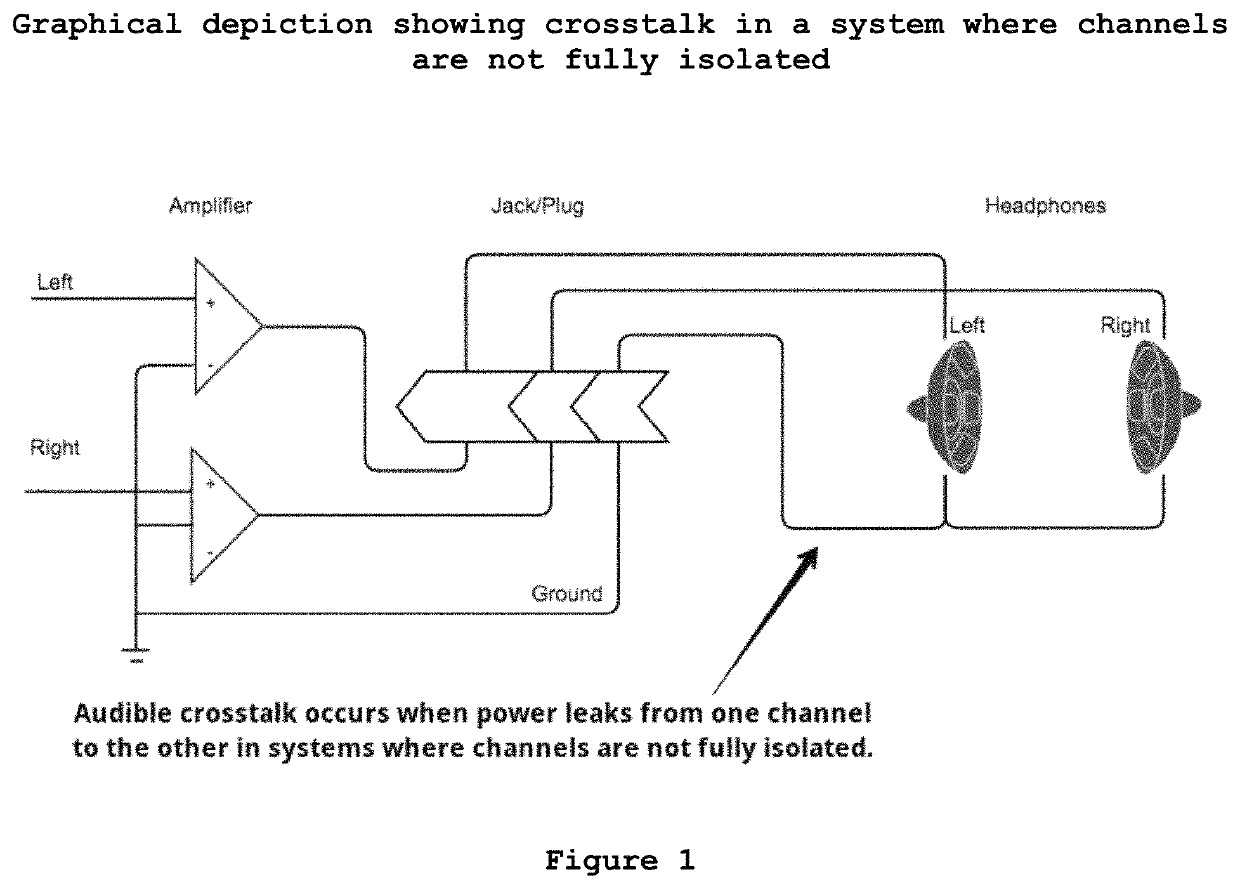
FIELD OF THE INVENTION[0001]The present invention relates to a method for reducing “crosstalk”, the unwanted transmission of signals between communication channels, in an audiometer. In particular, the present invention relates to a computer-implemented method for reducing crosstalk in a computer-based audiometer.BACKGROUND OF THE INVENTION[0002]Crosstalk, the unwanted transmission of signals between communication channels, in the context of hearing testing means that an unwanted audible signal is present on the inactive channel. ANSI / ASA S3.6-2010 regulates the maximum allowable levels of crosstalk for a compliant audiometer. Crosstalk occurs when power leaks from one channel to the other in systems where channels are not fully isolated (see FIG. 1).[0003]While purpose-built audiometers meet this standard through the use of hardware designed to electrically isolate the left and right channels, a software audiometer running on a computer or mobile device needs to take extra steps in...

Claims


Application Information

Patent Timeline
Patent Type & Authority Patents(United States)
IPC IPC(8): H04S1/00H04B3/32H04R5/04H04R5/033
CPCH04S1/005H04R5/04H04B3/32H04R5/033H04S2420/01H04S2400/01
Inventor MAJID, MICHAELBROMWICH, JULIANKOIVIKKO, HEIKKI
Owner SHOEBOX LTD
Learn More