Filling head injector for aerosol can with protective cover

a technology of injector and aerosol can, which is applied in the direction of packaging, packaging under special atmospheric conditions, liquid dispensing, etc., can solve the problems of high cost and inability to carry a filling machine, and achieve the effect of preventing excess spray

Active Publication Date: 2019-06-04
PRO FORM PRODS
View PDF15 Cites 0 Cited by
  • Summary
  • Abstract
  • Description
  • Claims
  • Application Information

AI Technical Summary

Benefits of technology

[0011]The present disclosure provides a filling gun which is used to add an activator to the aerosol can. The present disclosure relates to a filling gun assembly, similar in configuration to a caulking gun, which is used to manually inject an activator into an aerosol can without installing the can onto a pneumatic or manually operated aerosol can filling machine. The gun is inexpensive, portable, lightweight, easy to use, and can be easily transported to and used in machine shops, plants, body shops, etc. In contrast, a filling machine is typically not portable and is expensive.
[0012]In accordance with one aspect of the disclosure, a filling head gun has a housing, a handle assembly connected to the housing, and a filling head attached to the housing; wherein a plunger extends through an opening of the housing and an opening of an activator reservoir attached to the plunger. The reservoir is moved into position via the plunger to feed activator through the filling head to an aerosol can. A protective cover is provided on the filling head to protect the user and contain the spray.
[0013]In accordance with another aspect of the disclosure, a filling head and aerosol can assembly has: an aerosol can having a valve and dip tube, propellant, a coating, and a body; a filling head assembly comprising: a housing; a handle connected to said housing; a filling head attached to said housing via a piston rod; a tube containing activator which is connected to said piston rod wherein said handle is depressed to move said piston rod to feed activator through said tube into said filling head; and wherein said filling head is mounted onto said mounting cup, and a stem of said filling head seals on said valve mounting cup of said aerosol can. The filling head further has a protective cover for protecting the user and containing the spray. A platform extension is provided to aid retraction of the piston once it is fully inserted.

Problems solved by technology

In contrast, a filling machine is typically not portable and is expensive.

Method used


Image

  • Filling head injector for aerosol can with protective cover
  • Filling head injector for aerosol can with protective cover
  • Filling head injector for aerosol can with protective cover

Examples


Embodiment Construction

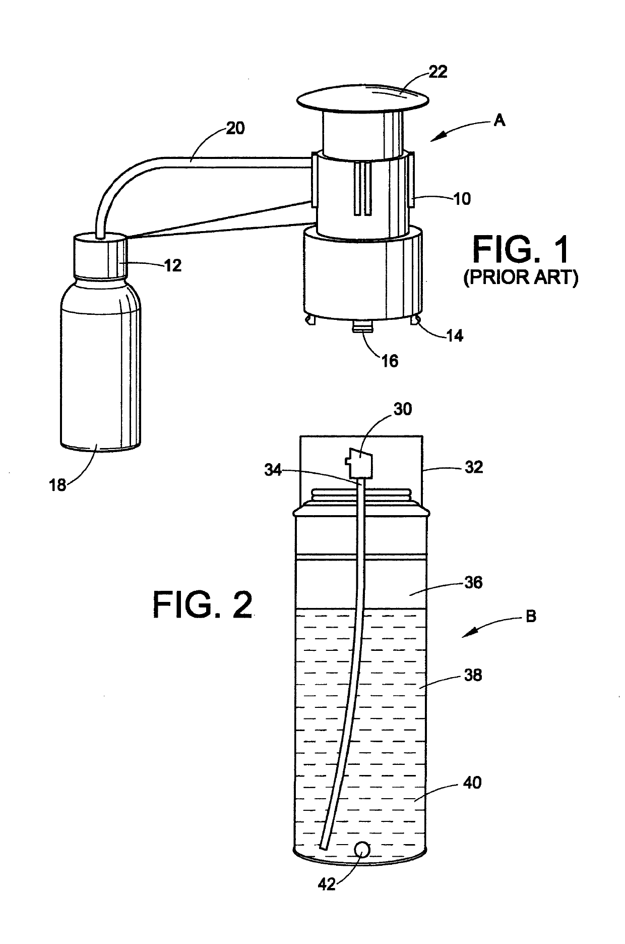
[0037]Referring to FIG. 1, the use of an existing manual spray pump A in an aerosol can includes the following steps: First, the spray head is removed from the aerosol can. Then, a washer 10 is removed from the side of the pump and inserted into the bottle flange 12. A collar lock 14 is turned counter-clockwise to expose prongs 16, which are snapped onto the top of the aerosol can. While the pump assembly is held in one hand, the lock collar is turned clockwise with the other hand to lower the pump onto the can. The collar is tightened snugly. The bottle 18 is filled with a reducer, catalyst or hardener and screwed into the bottle flange. A dip tube 20 has a length which is adjusted so that it is touching the bottom of the bottle. The can is placed on a hard surface. The plunger 22 is firmly pressed down to pump the material from the bottle into the aerosol can. The material in the bottle is sucked into the dip tube on the upward stroke and is pushed into the aerosol can on the down...


PUM


Abstract

A filling head gun assembly has a housing; a handle assembly connected to the housing; a filling head attached to the housing; and a plunger. The plunger extends through an opening of the housing and an activator reservoir attached to the plunger. The reservoir is moved into position to contact the filling head via the plunger to feed pressurized activator through the filling head to an aerosol can. A cover is releasably attached to an end of the filling head which provides a seal around the filling head.

Description

BACKGROUND OF THE DISCLOSURE[0001]The present disclosure relates to the art of filling pressurized containers. It finds particular application in conjunction with manually injecting activators into aerosol cans which have been previously charged with liquefied propellants and filled with paints, adhesives, resins or coatings and will be described with particular reference thereto. It is to be appreciated, however, that the present disclosure may also find application in conjunction with injecting other coating systems, including, but not limited to lubricants, fiberglass resins, SMC resins, adhesives, epoxy, urethane adhesives, and any other products which can be catalyzed or activated and dispensed from aerosol cans.[0002]There are two common methods for filling an aerosol container with propellant, namely, the “under the cup” method which lifts the valve mounting cup and the “pressure filling” method.[0003]More and more, the aerosol industry is resorting to “pressure filling” of t...

Claims


Application Information

Patent Timeline
Patent Type & Authority Patents(United States)
IPC IPC(8): B65D83/42B65B31/00B65B39/02
CPCB65D83/425B65B39/02B65B31/003
Inventor SPECK, JAMES H.
Owner PRO FORM PRODS
Why Eureka
Try Eureka