
Tubular mezzanine and conveyor support structures and stiffener brackets for assembly thereof

a technology for supporting structures and mezzanines, which is applied in the direction of fastening means, conveyor parts, rod connections, etc., can solve the problems of high welding cost, difficult to ensure, and requiring skilled labor, and achieve the effect of increasing the rigidity of the structure and strengthening the rigidity of the join

Active Publication Date: 2019-03-26
ROACH MFG CORP
View PDF20 Cites 0 Cited by
  • Summary
  • Abstract
  • Description
  • Claims
  • Application Information

AI Technical Summary

Benefits of technology

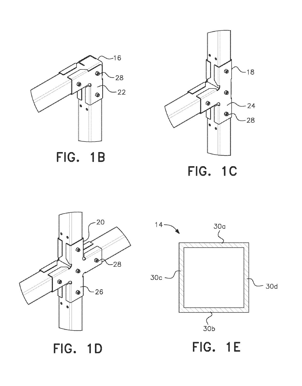
The present invention provides a support structure for conveyors and mezzanines that includes interlocking joints between tubular members reinforced with stiffener brackets. The stiffener brackets securely clamp the tubular members in place and reinforce the rigidity of the joint. The configuration of the structure can be more easily modified than a conventional welded support structure, and the tubular members can be arranged to form elbow joints, tee joints and cross joints. The flanges of one of the two interlocked tubular members extend to be generally parallel with and adjacent the adjoining sides of a first one of the interlocked tubular members while the flanges on the other of the two arms extend to be generally parallel with and adjacent the adjoining sides of the second one of the interlocked tubular members, so that the bracket and its flanges effectively create a reinforcing connection between the first and second tubular members that supplements the primary connection formed by the nested interlocked relationship.

Problems solved by technology

In orienting the support members prior to welding it can be difficult to ensure that the support members are properly positioned with good joint angles, generally in perpendicular relationship, between the support members.
Further, welding is expensive, requiring skilled laborers to ensure the welds are done properly.
Finally, once the welded joints are completed, the finished joints are essentially permanent such that the resulting support structure is not easily modified or disassembled.

Method used


Image

  • Tubular mezzanine and conveyor support structures and stiffener brackets for assembly thereof
  • Tubular mezzanine and conveyor support structures and stiffener brackets for assembly thereof
  • Tubular mezzanine and conveyor support structures and stiffener brackets for assembly thereof

Examples


Embodiment Construction

[0061]In explaining in detail the preferred embodiments for joints used in the support structure of the invention, it is to be understood that the embodiments are given by way of illustration only. It is not intended that the invention be limited in its scope to the details of construction and arrangement of components set forth in the following description or illustrated in the drawings. Also, in describing the preferred embodiments, specific terminology will be resorted to for the sake of clarity. It is to be understood that each specific term includes all technical equivalents which operate in a similar manner to accomplish a similar purpose.

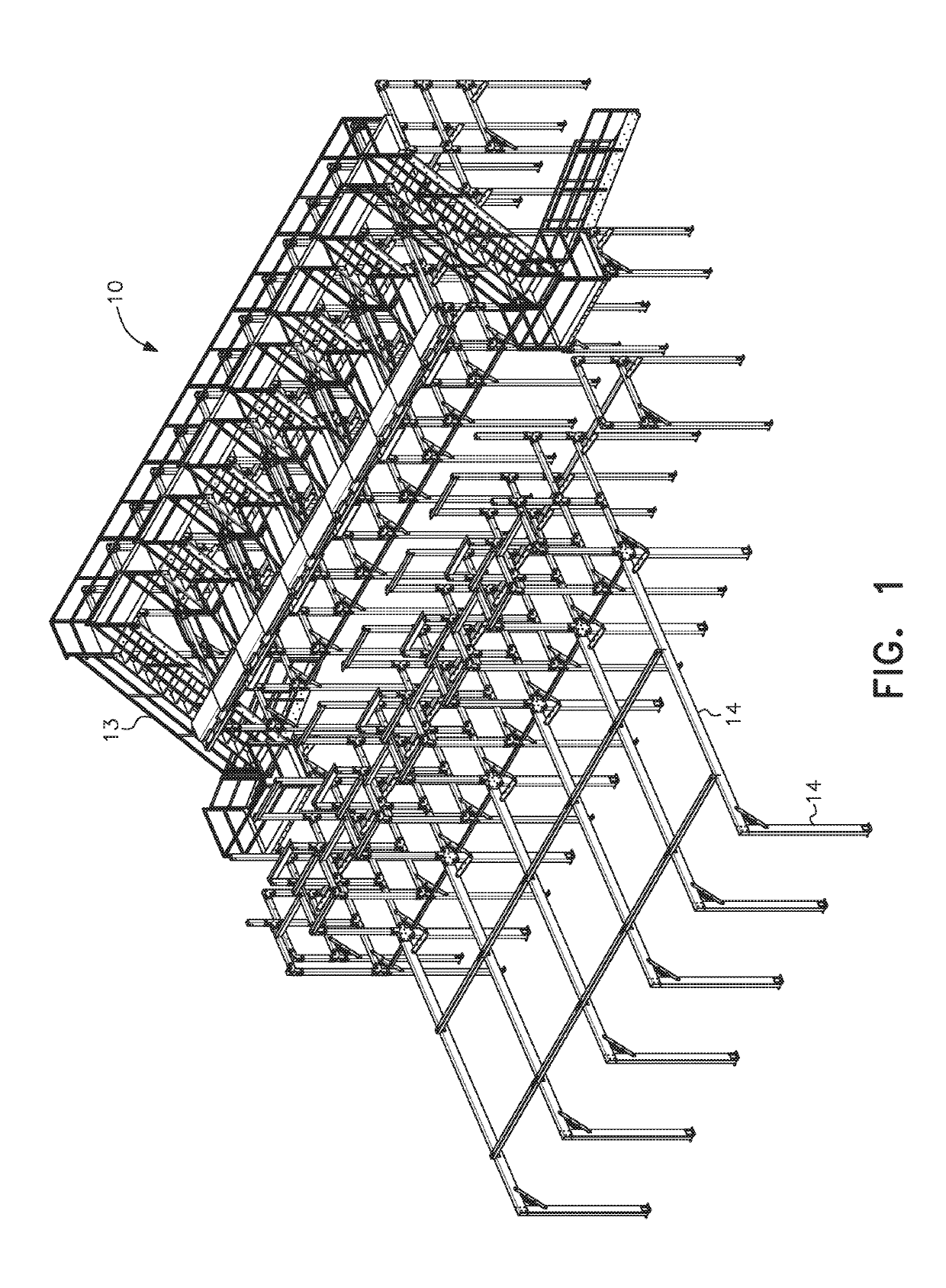
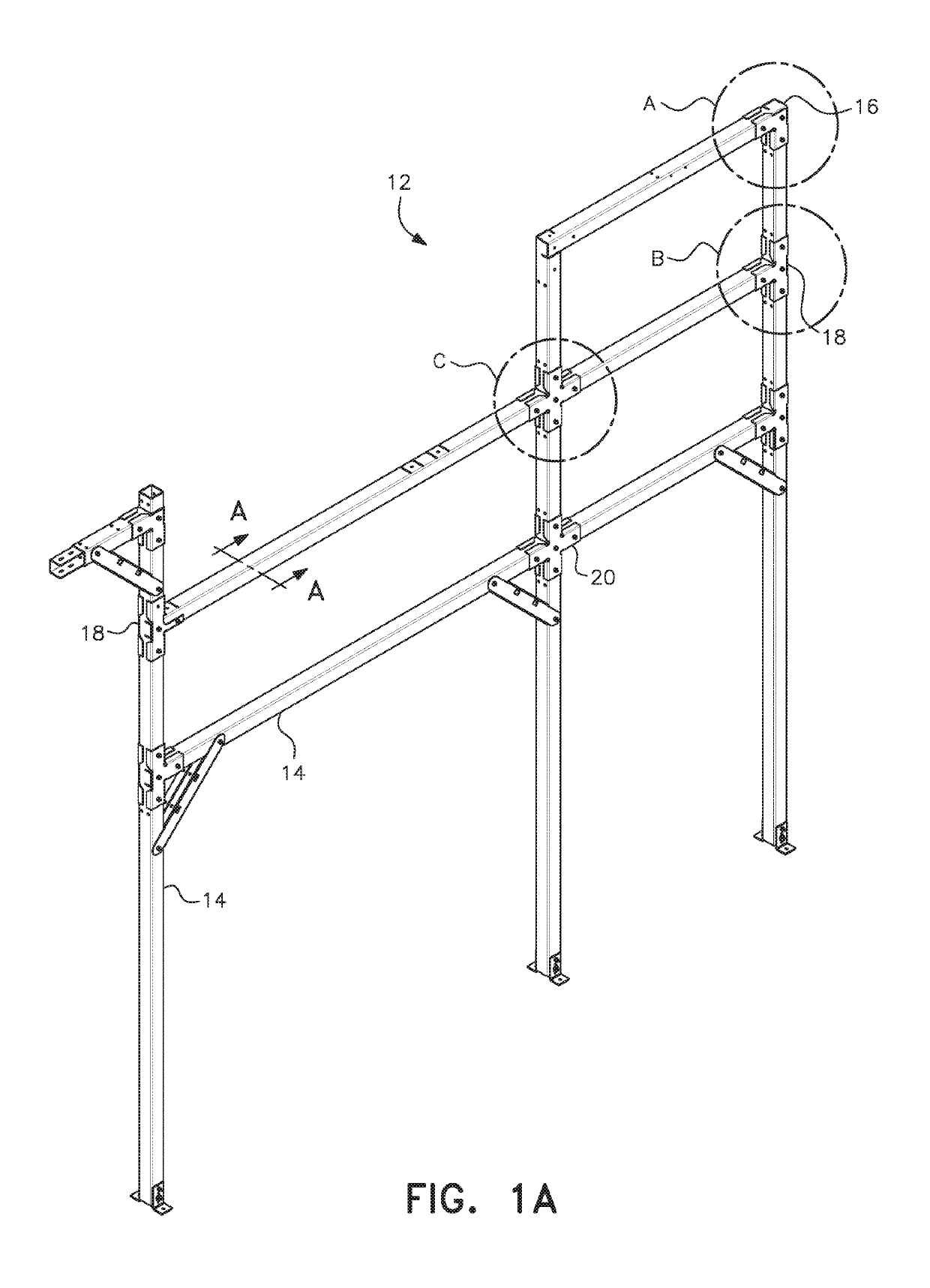
[0062]As shown in FIG. 1, the present invention is directed to a support structure for conveyors and mezzanines, generally designated by reference numeral 10. The support structure is comprised of a plurality of subassemblies like that shown in FIG. 1A and generally designated by reference numeral 12. A mezzanine 13 is shown being supported a...


PUM


Abstract

An interlocking system of tubular members is provided for support of conveyors and mezzanines, each tubular member having cutouts and slots for assembly with other of the tubular members to form elbow joints, tee joints and cross joints, and stiffener brackets to reinforce the interlocking joints to form a strong support structure without the need for welding. A mezzanine conveyor assembly is also provided that includes a support structure constructed of non-welded interlocking tubular members reinforced with stiffener brackets, with a mezzanine / platform and at least one conveyor supported on the support structure.

Description

BACKGROUND OF THE INVENTION[0001]Field of the Invention[0002]The present invention is related to the field of support structures for conveyors and mezzanines and, more particularly, to an interlocking system of tubular members and joint stiffening brackets for mezzanine and conveyor supports that is assembled without the need for welding, and a mezzanine and conveyor assembly with such a support structure.[0003]Description of the Related Art[0004]Mezzanines often have associated conveyors, such as mezzanine floor incline conveyors, to move products between floors in a building. Conveyors assembled with mezzanines provide faster transport of goods and / or equipment between floors and are simpler to operate and usually less expensive than a goods lift or elevator, making mezzanine conveyor assemblies a good alternative to these more permanent constructions. Mezzanine and conveyor support structures are currently constructed by welding a plurality of members to one another at their poin...

Claims


Application Information

Patent Timeline
Patent Type & Authority Patents(United States)
IPC IPC(8): B65G41/00F16B7/04
CPCF16B7/0446B65G41/006F16B7/0493F16B7/185
Inventor ROACH, SR., MICHAEL W.KAIN, CHRISTOPHER E.
Owner ROACH MFG CORP
Learn More