A screw thread driving polyhedral supersonic micro motor with pre-pressure mechanism
A pre-pressure mechanism and micro-motor technology, applied in the direction of generator/motor, piezoelectric device/electrostrictive device, piezoelectric effect/electrostrictive or magnetostrictive motor, etc., can solve the problem of unstable operation and impact There will be problems such as running accuracy and return clearance, so as to achieve the effect of stable performance and simple structure
- Summary
- Abstract
- Description
- Claims
- Application Information
AI Technical Summary
Problems solved by technology
Method used
Image
Examples
Embodiment 1
[0034] Embodiment 1: Thread-driven polyhedron ultrasonic micromotor with pretension (tension) force spring
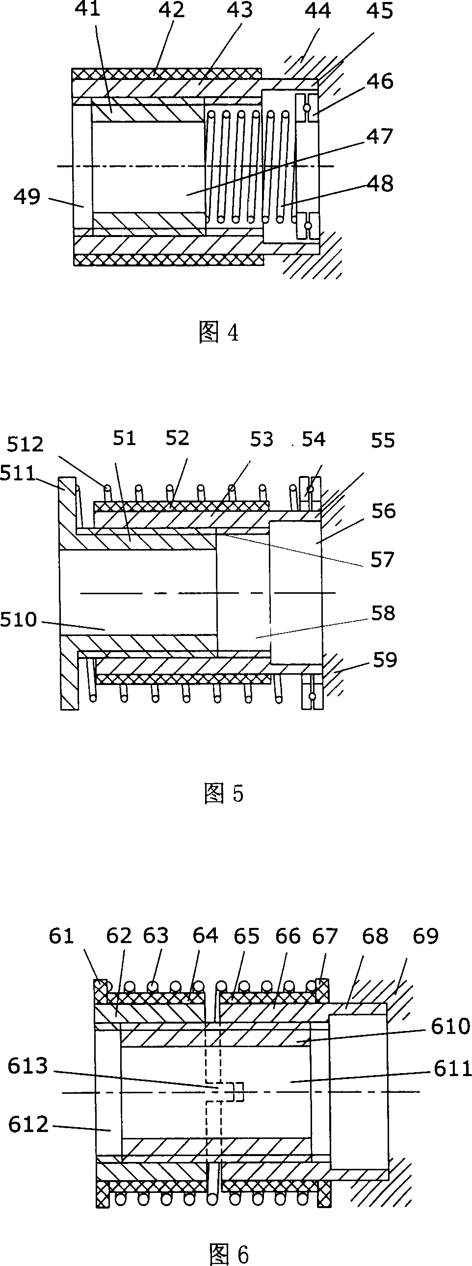
[0035] The thread-driven polyhedron ultrasonic micromotor structure with pretension (tension) force spring of this embodiment, as shown in FIG. The ultrasonic motor includes a rotor 41 and a stator 43, and 12 piezoelectric elements 42 are attached to the stator 43 (the piezoelectric elements 42 can be sheet-shaped, arc-shaped sheet, column-shaped or various polyhedrons, integral annular or conical piezoelectric elements). The stator and rotor have threads that cooperate with each other. The cross-section of the thread can be in various forms such as triangle, trapezoid, rectangle, and convex surface, and their combinations. The form of the thread can be continuous, segmented, or a curve with a specific trajectory.
[0036] One end of the stator is provided with a thin-wall isolation strip 45, and one end of the isolation strip is fixed on the base 44, and the function o...
Embodiment 2
[0039] Embodiment 2: Thread-driven polyhedron ultrasonic micromotor with rotor cap and pretension (tension) force spring
[0040] As shown in Figure 5, the main difference between this embodiment and Embodiment 1 is: in this embodiment, the pretension (tension) force spring 512 is placed on the outside of the stator 53, and one of the two supporting ends of the spring 512 is on the rotor. On the cap 511 , one is on the bearing 54 , the bearing 54 can be arranged on the base 59 , and can also be arranged on the stator 53 to reduce the frictional force when the rotor 511 rotates. The form of the spring can also be an elastic sheet, and the form of the bearing can also be a groove or a slide sheet containing balls. 57 is a wear-resistant coating.
[0041] Another structure of the pre-pressure mechanism in this embodiment is: two magnetic rings can be used instead at the section between the stator 53 and the rotor 511; or one is a magnetic ring and the other is a ferromagnetic ri...
Embodiment 3
[0042]Embodiment 3: Double-stator thread-driven polyhedron ultrasonic micromotor with pretension (tension) force spring
[0043] The double-stator thread-driven polyhedral ultrasonic micromotor with pretension (tension) force spring used in this embodiment is shown in FIG. 6 . The stators 62 and 66 drive the rotor 610 to move at the same time, and one end of the stator 66 is fixed on the base 69 by an isolation belt 68, and a spring 63 is used between the two stators to provide a pretension (tension) force, so that the threads between the stator and the rotor are mutually Press tight. Blocking blocks 61 and 67 are pasted on the stators 62, 66, and block the two ends of the spring. The blocking material can be metal or non-metal. The two stators are positioned through the slot 613 so that the stator 62 does not rotate.
[0044] When this embodiment is applied, the optical lens group can be installed in the rotor cavity 611 and / or the stator cavity 612 . After the alternatin...
PUM
 Abstract
Description
Claims
Application Information
 - R&D
- Intellectual Property
- Life Sciences
- Materials
- Tech Scout
- Unparalleled Data Quality
- Higher Quality Content
- 60% Fewer Hallucinations
Browse by: Latest US Patents, China's latest patents, Technical Efficacy Thesaurus, Application Domain, Technology Topic, Popular Technical Reports.
© 2025 PatSnap. All rights reserved.Legal|Privacy policy|Modern Slavery Act Transparency Statement|Sitemap|About US| Contact US: help@patsnap.com


