Electric shedding apparatus for loom
A shedding device, electric technology, applied in the direction of looms, other shedding mechanisms, weaving auxiliary equipment, etc., can solve problems such as incomprehensible, heavy load, damage to the motor or transmission system, etc.
- Summary
- Abstract
- Description
- Claims
- Application Information
AI Technical Summary
Problems solved by technology
Method used
Image
Examples
Embodiment 1
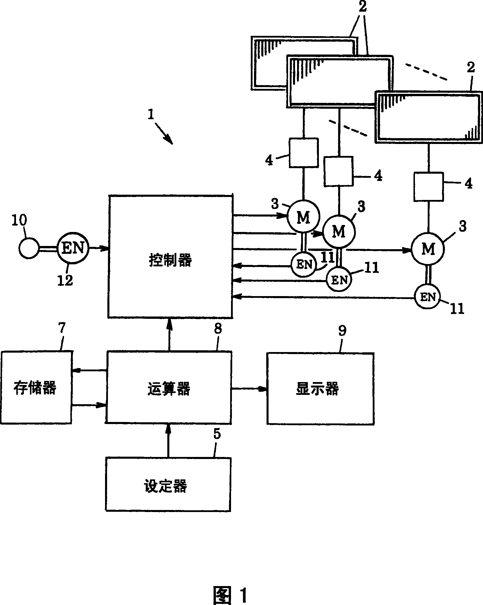
[0039] The first embodiment is based on inputting the opening motion conditions of each palm frame 2 to the setter 5. When the palm frame 2 is driven under the set opening motion conditions, the motor 3 corresponding to each palm frame 2 is obtained. An example of the load applied on and displayed on the display 9.
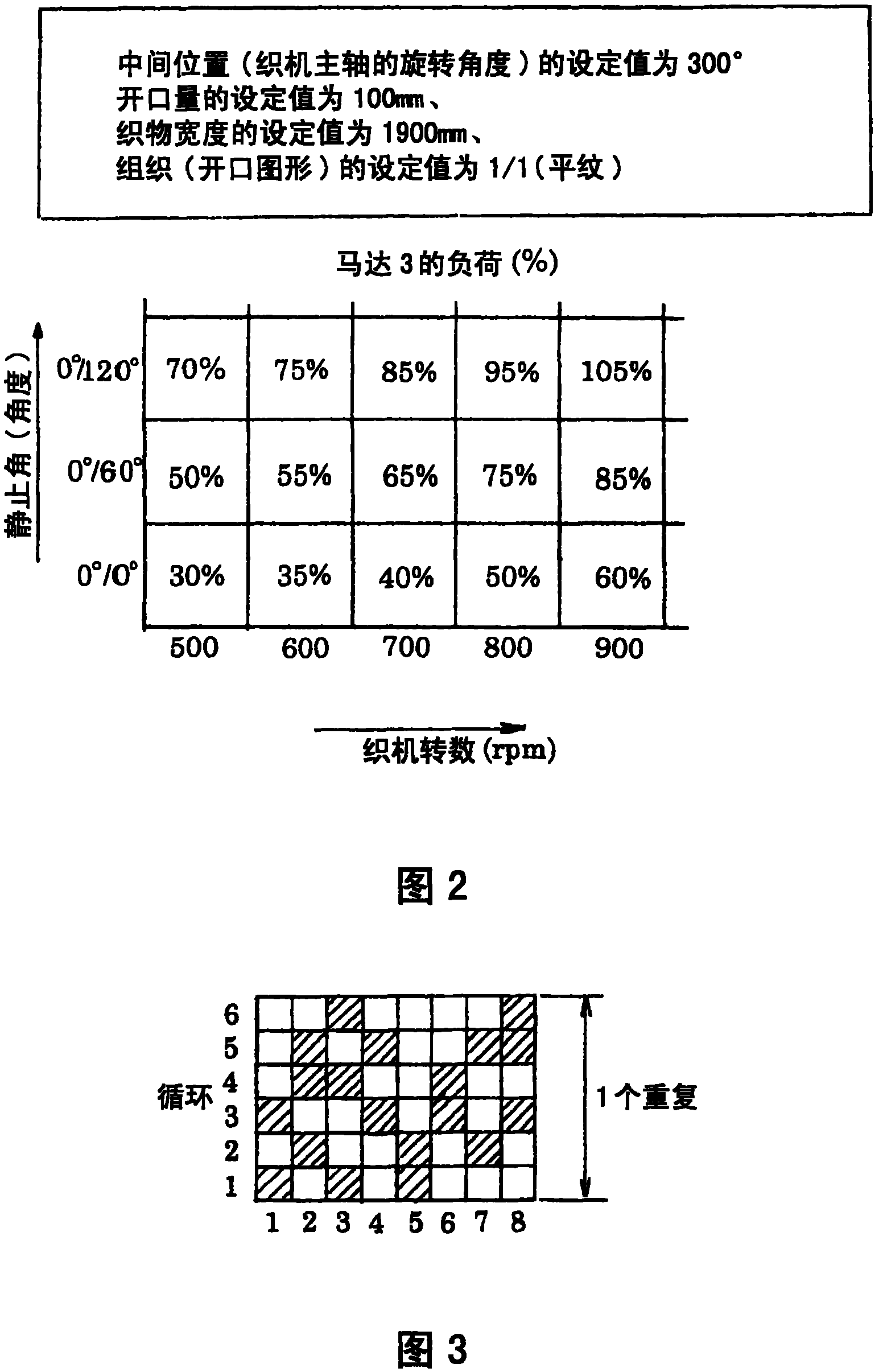
[0040] In order to display the load of the motor 3, a plurality of databases corresponding to a plurality of opening motion conditions, for example, each weave (tissue) are stored in the memory 7. This database is based on the actual weaving carried out under each shedding movement condition, and accumulates the data of the actual load of the motor 3 when the palm frame 2 is driven under each shedding movement condition. figure 2 The distribution form shown is expressed in the form of a table.
[0041] figure 2 The database, as shown in the box in the upper paragraph, is the middle position of the top dead center and bottom dead center (rotation angle of the loom mai...
Embodiment 2
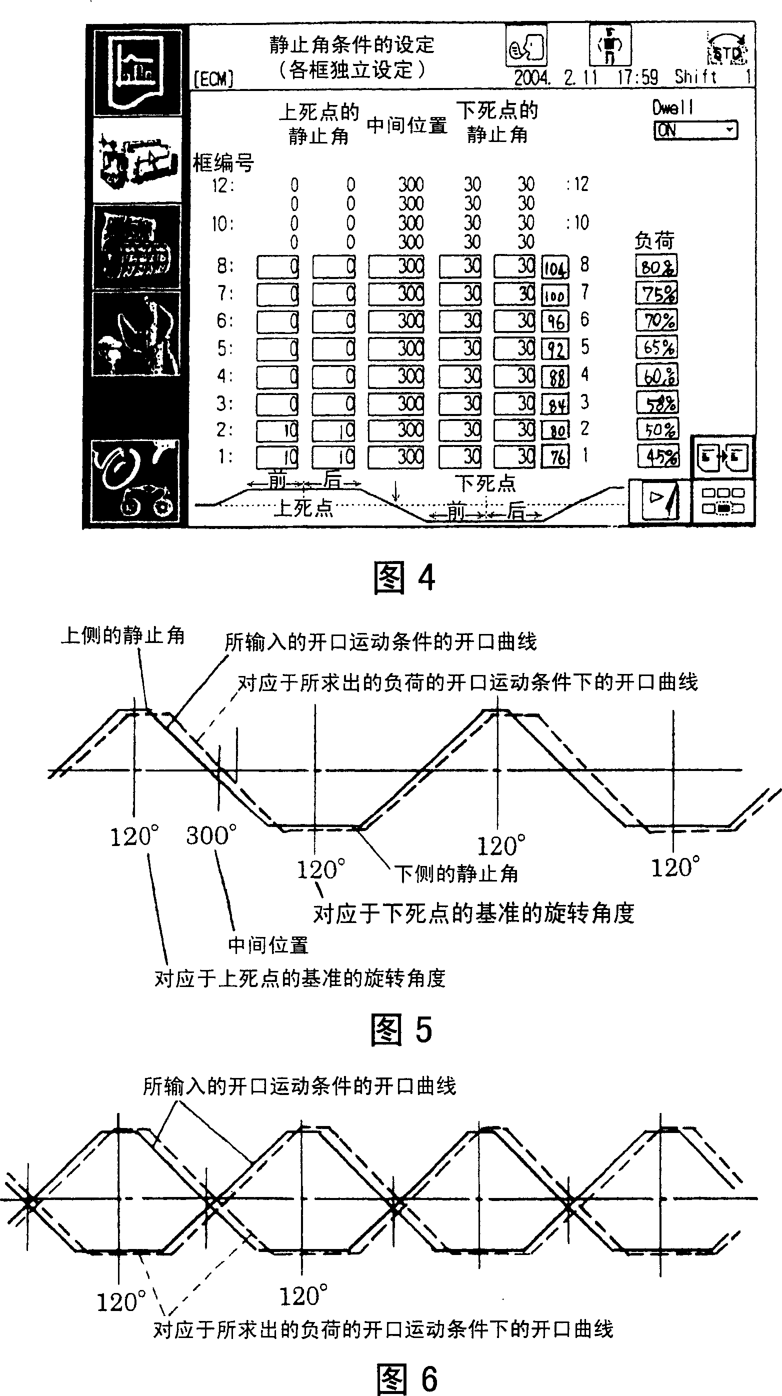
[0062] In the second embodiment, in addition to the input of the opening motion conditions, the input of the allowable load value of the motor 3 is also used. According to the set opening motion conditions, the database and the load allowable value, the load contraction of the motor 3 can be obtained below the allowable value. Examples of opening movement conditions and displayed on the display 9.
[0063] On the setting device 5, use Figure 4 In the display screen shown, input the allowable value of the load of the motor 3, such as "80%", and input as the opening movement condition, for example, the middle position of the frame number 1 is 290° and the opening amount is 120 mm. When these set values are input to the setter 5, the arithmetic unit 8 extracts recommended opening motion conditions that are lower than the input load allowance value from the database stored in the memory 7.
[0064] Specifically, when the opening movement conditions stored in the database of the memo...
Embodiment 3
[0071] Example 3, as described in the above-mentioned Example 2, is that in addition to the open motion conditions, the load allowance of the motor 3 can be input and the open motion conditions that shrink it below the allowable value of the load of the motor 3 can be obtained. The obtained recommended opening motion conditions are output to the controller 6 and the recommended opening motion conditions are automatically set in the controller 6 as an example.
[0072] Therefore, the arithmetic unit 8 obtains the recommended opening motion condition, inputs the set value of the recommended opening motion condition to the controller 6, and automatically sets it there. This eases the burden on the operator to adjust the loom. The display 9 displays the calculated recommended opening motion conditions with numerical values, curves (opening curves), or a combination of numerical values and curves (opening curves), but in Embodiment 3, since the controller 6 automatically sets The s...
PUM
 Abstract
Description
Claims
Application Information
 - R&D
- Intellectual Property
- Life Sciences
- Materials
- Tech Scout
- Unparalleled Data Quality
- Higher Quality Content
- 60% Fewer Hallucinations
Browse by: Latest US Patents, China's latest patents, Technical Efficacy Thesaurus, Application Domain, Technology Topic, Popular Technical Reports.
© 2025 PatSnap. All rights reserved.Legal|Privacy policy|Modern Slavery Act Transparency Statement|Sitemap|About US| Contact US: help@patsnap.com


