
Device for detachably linking a wiper blade with a wiper arm

A technology for connecting elements, wiper blades, applied in the field of connecting elements

Inactive Publication Date: 2006-02-22
ROBERT BOSCH GMBH
View PDF3 Cites 6 Cited by
  • Summary
  • Abstract
  • Description
  • Claims
  • Application Information

AI Technical Summary

Problems solved by technology

But for this the wiper arm must be folded away from the window glass

Method used


Image

  • Device for detachably linking a wiper blade with a wiper arm
  • Device for detachably linking a wiper blade with a wiper arm
  • Device for detachably linking a wiper blade with a wiper arm

Examples


Embodiment Construction

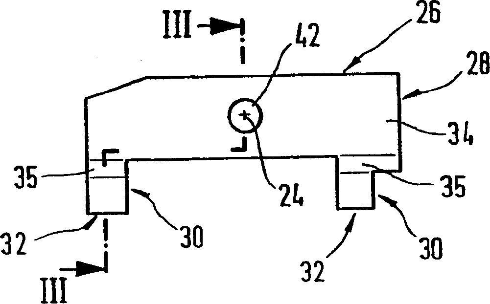
[0041] FIG. 1 shows a side view of a free end of a wiper arm 10 , on which a wiper blade 12 is articulated via a hinge connection 13 , to which the other end, not shown, is driven, such that That is, the wiper blade can pivot in the direction of the double arrow 14 . The wiper blade has a strip-shaped longitudinally extending, curved, spring-elastic support element 16 on its strip-shaped surface, on its lower, concave strip-shaped surface 17 facing the window pane 20 parallel to the longitudinal axis. A rubber-elastic wiper strip 18 is arranged, also extending longitudinally in the form of a strip. The surface of the motor vehicle window to be wiped is indicated in FIG. 1 by a dotted line 20 . Since the dot-dash line 20 shows the most severe curvature of the window pane surface, it should be clearly shown that the curvature of the unloaded wiper blade 12 with its two ends abutting on the window pane 20 is greater than Maximum curvature of the window glass. With pressure act...


PUM


Abstract

A device is proposed which is used to detachably connect a wiper blade (12) to clean windows, particularly of motor vehicle. On the outer convex band surface (15) of the supporting element (16) sits a connecting element (26), which features two parallel wall surfaces (36) that are aligned in a vertical plane on the band surface and extend in the longitudinal direction of the wiper blade and that a pivot pin (42) projects from each wall surface, whereby the longitudinal axes of the two pivot pins are aligned with one another. An especially simple embodiment of the articulated connection with an integrated connecting device is achieved if an adapter (66 or 166) that can move in a pendulum fashion is positioned on the two pivot pins of the connecting element (26), and said adapter features means to connect to the wiper blade holder (50 or 150) of the wiper arm (10).

Description

[0001] This application is a divisional application whose application number is 018216307 and the title of the invention is "A device for detachably connecting a wiper blade to a wiper arm". technical field [0002] The invention relates to a connecting element for the articulated connection of a wiper blade and a wiper arm. Background technique [0003] In the wiper blade concerned, the support element ensures that the contact force of the wiper blade exerted by the wiper arm on the window pane is distributed as evenly as possible for the entire wiper area swept by the wiper blade. Due to the corresponding curvature of the unloaded support element—that is, when the wiper blade does not rest against the windshield—even if the radius of curvature of the spherically curved windshield changes at each wiper blade position However, the ends of the wiper strips, which are completely in contact with the windshield when the wiper blades are actuated, are also loaded by the bearing e...

Claims


Application Information

Patent Timeline
Patent Type & Authority Applications(China)
IPC IPC(8): B60S1/40B60S1/38
CPCB60S1/3856B60S1/3868B60S1/4038B60S2001/4051B60S2001/4054B60S1/40B60S1/3879B60S1/4045
Inventor M·韦伯H·拉普G·克拉梅J·马耶W·莱特斯奇M·巴塞奥托D·赫林克西P·德布洛克H·维雷斯特P·霍斯比克西F·布里斯奇E·温德莫德斯C·威姆斯I·奥普特鲁德特H·比伦R·韦托根J·格林
Owner ROBERT BOSCH GMBH
Learn More