Safety injection needle assembly and safety syringe
A technology of injection needle and safety type, which is applied in the field of medical equipment, and can solve the problem of accidental injury and accidental injury by the needle tube of the injection needle when it is set back on the outer wall of the needle seat; when the syringe is ready to use, the injection needle passes through its needle The inner wall of the needle seat hole of the seat is sleeved and fixed on the cone head of the syringe to achieve the effect of preventing accidental injury, reasonable structure and good safety
- Summary
- Abstract
- Description
- Claims
- Application Information
AI Technical Summary
Problems solved by technology
Method used
Image
Examples
Embodiment 1
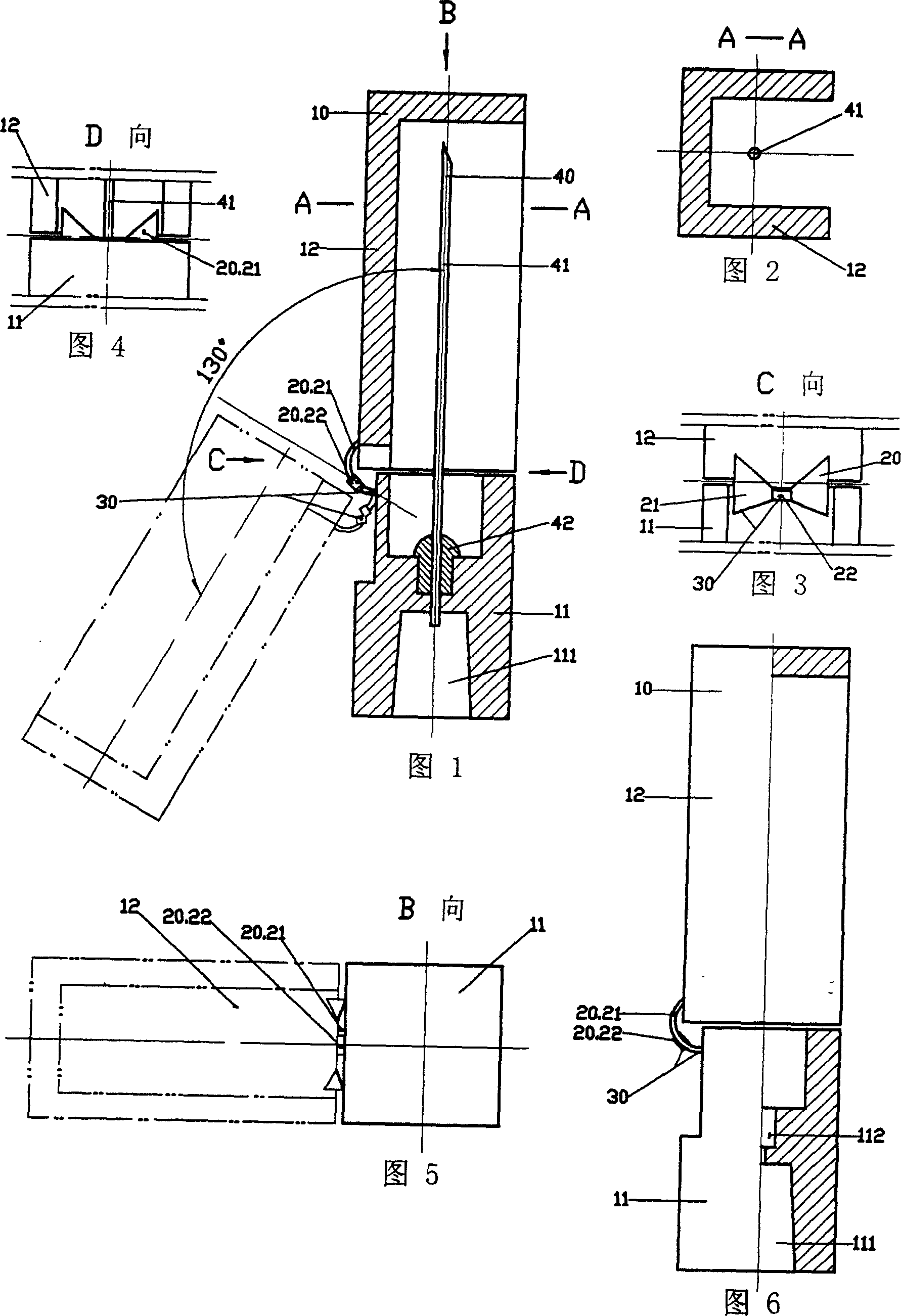
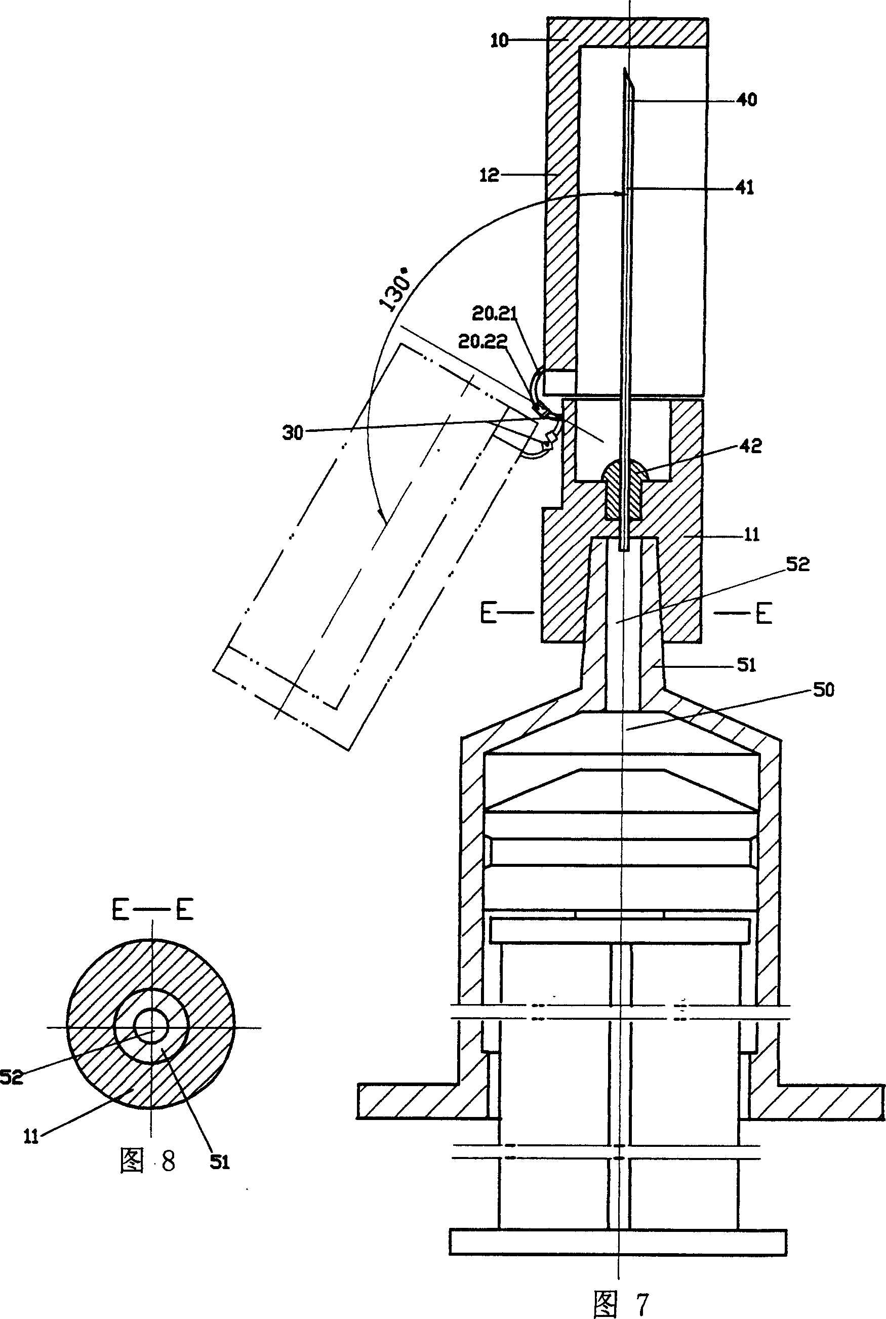
[0042] Referring to Fig. 1 to Fig. 8, the materials used in the safety injection needle assembly of this embodiment comply with national standards. The safety type injection needle assembly of the present embodiment has a safety sheath 10 and an injection needle 40; the safety sheath 10 is an integral part composed of a base 11, a shield 12 and a hinge mechanism 20; the base 11 of the safety sheath 10 is designed There are positioning holes 111; the hinge mechanism 20 of the safety sheath 10 is arranged between the base 11 and the shield 12, and the base 11 is connected with the shield 12 through the hinge mechanism 20; the opposite of the shield 12 of the safety sheath 10 The position on one side of the hinge mechanism 20 is an open position; the hinge mechanism 20 has an overturn support part 30, and the shield 12 of the safety sheath 10 can be rotated relative to the axial centerline of the injection needle 40 through the overturn support part 30 of the hinge mechanism 20. ...
Embodiment 2
[0046] See Figures 9 to 13, the hinge mechanism 20 of the safety injection needle assembly of this embodiment is composed of a leaf spring 23 and two hinges 24, the hinges 24 are arranged on both sides of the leaf spring 23, and each hinge 24 is provided with a turning part 241 and fixed portion 242, the upper section of the turning portion 241 of each hinge 24 and the top of the leaf spring 23 are connected with the shield 12, the root of the fixed portion 242 of each hinge 24 and the leaf spring 23 is connected with the base 11, and the leaf spring 23 and the roots of the turning parts 241 of the hinges 24 jointly constitute the turning support part 30 .
[0047] See Figure 9 and Figure 13, the use process of the safety injection needle assembly of this embodiment is basically the same as that of Embodiment 1, the safety injection needle assembly is sleeved and fixed on the inner wall of the positioning hole 111 of the base 11 of the safety sheath 10 On the conical head 51 o...
Embodiment 3
[0050] See Fig. 14 to Fig. 18, the hinge mechanism 20 of the safety injection needle assembly of this embodiment is composed of a hinge 24 and two leaf springs 23, the leaf springs 23 are arranged on both sides of the hinge 24, and the hinge 24 is provided with a turning part 241 And fixed portion 242, the upper section of the turning portion 241 of hinge 24 and the top of each leaf spring 23 are connected with shield 12, the root of fixed portion 242 of hinge 24 and each leaf spring 23 is connected with base 11, the hinge 24 The root of the turning portion 241 and the roots of each leaf spring 23 together constitute the turning support part 30 .
[0051] See Fig. 14, Fig. 15 and Fig. 18, when the turning part 241 of the hinge 24 is in contact with the fixed part 242, the contact plane is parallel to the axial center line of the injection needle 40; the reason why the elastic force of the leaf spring 23 makes the shield 12 turn When the open position is reached, the angle of o...
PUM
 Abstract
Description
Claims
Application Information
 - R&D Engineer
- R&D Manager
- IP Professional
- Industry Leading Data Capabilities
- Powerful AI technology
- Patent DNA Extraction
Browse by: Latest US Patents, China's latest patents, Technical Efficacy Thesaurus, Application Domain, Technology Topic, Popular Technical Reports.
© 2024 PatSnap. All rights reserved.Legal|Privacy policy|Modern Slavery Act Transparency Statement|Sitemap|About US| Contact US: help@patsnap.com


