
Assembling structure and method for pointer of instrument

A technology of assembling structure and pointer, applied in the direction of instruments, physical instruments, measuring devices, etc., can solve the problem that the through hole is easily touched by other components

Inactive Publication Date: 2004-09-22
CALSONIC KANSEI CORP
View PDF1 Cites 5 Cited by
  • Summary
  • Abstract
  • Description
  • Claims
  • Application Information

AI Technical Summary

Problems solved by technology

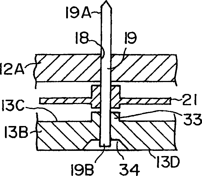
Therefore, if the lower end portion of the pointer is inserted into the through hole, there is a problem that the front edge of the lower end portion of the pointer shaft protrudes from the bottom surface of the lower cover.
Moreover, for the prior art, the opening edge portion of the through hole is at the same height as the bottom surface of the lower cover, and the edge of the through hole is easily touched by other parts, and the burrs will enter the through hole, so that the stable rotation of the pointer shaft will be reduced. bring problems

Method used


Image

  • Assembling structure and method for pointer of instrument
  • Assembling structure and method for pointer of instrument
  • Assembling structure and method for pointer of instrument

Examples


Embodiment Construction

[0022] Hereinafter, an embodiment of the present invention will be described with reference to the accompanying drawings.

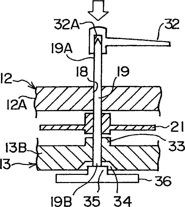
[0023] Figures 4 to 6 shows an instrument according to this embodiment incorporating a stepper motor, Figure 4 is a perspective view of the appearance, Figure 5 is an exploded perspective view, Image 6 is along Figure 4 A cross-sectional view of line A-A.

[0024] like Figures 4 to 6 As shown, an instrument 10 incorporating a stepping motor includes a housing 11 made of synthetic resin including an upper cover 12 and a lower cover 13 . A pair of holes 14 are provided on the upper wall 12A of the upper cover 12 , and a pair of protrusions 15 corresponding to the holes 14 are provided on the side wall 13A of the lower cover 13 . The upper cover 12 is aligned with the lower cover 13 by fitting the protrusion 15 into the hole 14 . The tab 16 is located on the side wall 12B of the upper cover 12 , and the protrusion 17 is located on the side wall 13...


PUM


Abstract

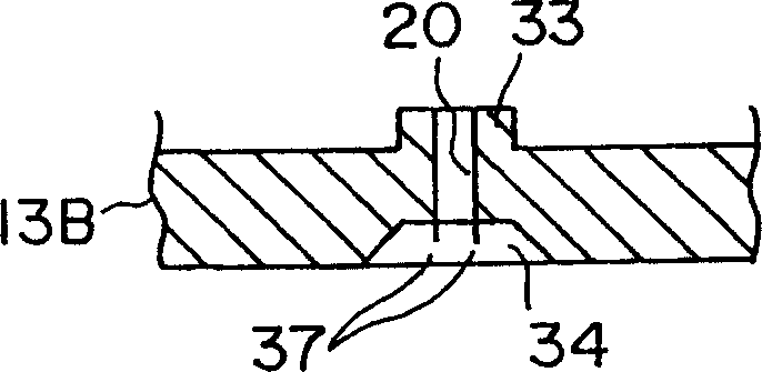
A assembling structure of an indicating needle for an instrument includes a case body having an upper case and a lower case (13), an indicating needle shaft (19) rotatably pivoted by the upper case and the lower case, and a top portion (19A) of the indicating needle shaft is projected to outside from the upper caser (13), and an indicating needle (32) provided on the projection. A concave portion (34) is provided on a shift supporting portion of the indicating needle shaft (19) in a bottom surface of the lower case, a lower end portion (19B) of the indicating needle shaft (19) is projected into the concave portion (34), and the projection amount is smaller than the depth of the concave portion (34).

Description

technical field [0001] The invention relates to an assembly structure and an assembly method for installing a pointer on a pointer shaft in an instrument combined with a stepping motor. Background technique [0002] Generally, instruments for vehicles, such as speedometers and the like, are housed in a housing 3, which includes an upper cover 1 and a lower cover 2, and pointers 5 are rotatably pivoted at upper portions relative to the upper cover 1, respectively. Rotate, pivot rotatably relative to the lower cover 2 in the lower part, and also have a gear 4 in the middle part of the pointer. An upper end portion 5A of the pointer shaft 5 protrudes outward from the upper cover 1, and a pointer 6 is provided thereon. [0003] Usually, the pointer 6 is assembled to the upper end portion 5A of the pointer shaft 5 by a press-fit mounting method. That is, the usual housing 3 is placed flat on a base (not shown), and the pointer shaft 5A is directed in a direction perpendicular t...

Claims


Application Information

Patent Timeline
Patent Type & Authority Applications(China)
IPC IPC(8): G01D13/22B60K35/00G01D11/24H02K37/16
CPCG01D11/24Y10S116/06G01D2213/10
Inventor 阿部尚太郎高桥英之
Owner CALSONIC KANSEI CORP
Learn More