Structure for addressing electrodes in plasma panel display

A flat-panel display, addressing electrode technology, applied in circuits, discharge tubes, electrical components, etc., can solve the problems of high probability of disconnection, low current, slow writing speed, etc., to improve current resistance and increase writing speed. , to avoid the effect of overloading

Inactive Publication Date: 2007-02-28
CHUNGHWA PICTURE TUBES LTD
View PDF4 Cites 0 Cited by
  • Summary
  • Abstract
  • Description
  • Claims
  • Application Information

AI Technical Summary

Problems solved by technology

[0006] However, in the traditional structure, the shape of the addressing electrodes is designed to be equal in width, and in order to avoid excessive loading on the writing side due to excessive addressing capacitance, the electrode width must be reduced as much as possible, and the width of the electrodes must not be too wide, which will cause the writing speed to be too slow , and it is a single wire design, which can withstand a small current and a high probability of disconnection

Method used


Image

  • Structure for addressing electrodes in plasma panel display
  • Structure for addressing electrodes in plasma panel display
  • Structure for addressing electrodes in plasma panel display

Examples


Embodiment Construction

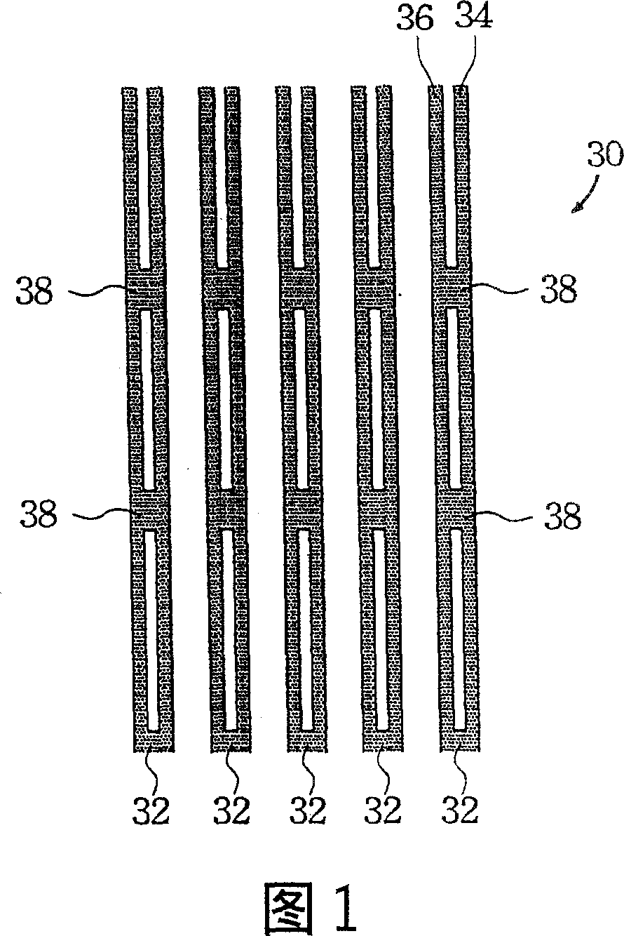
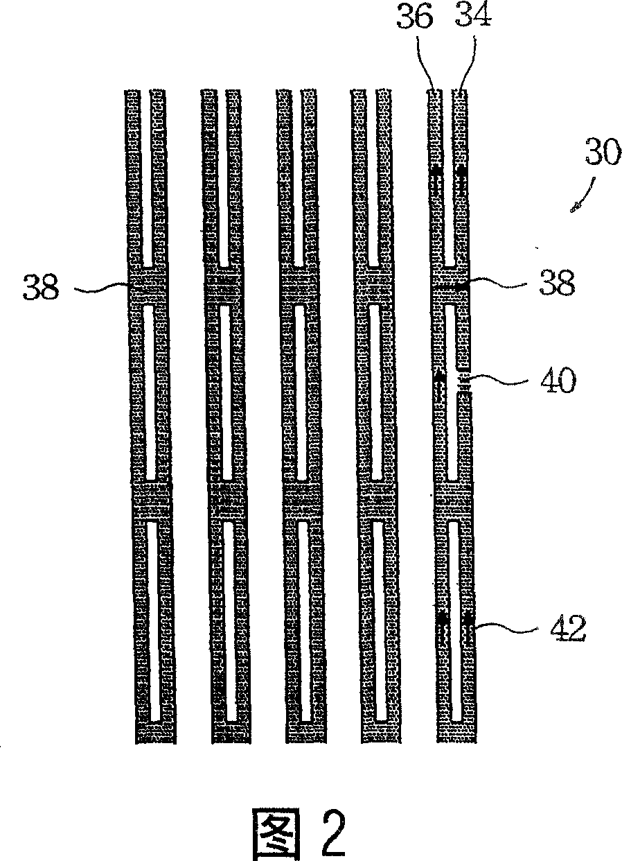
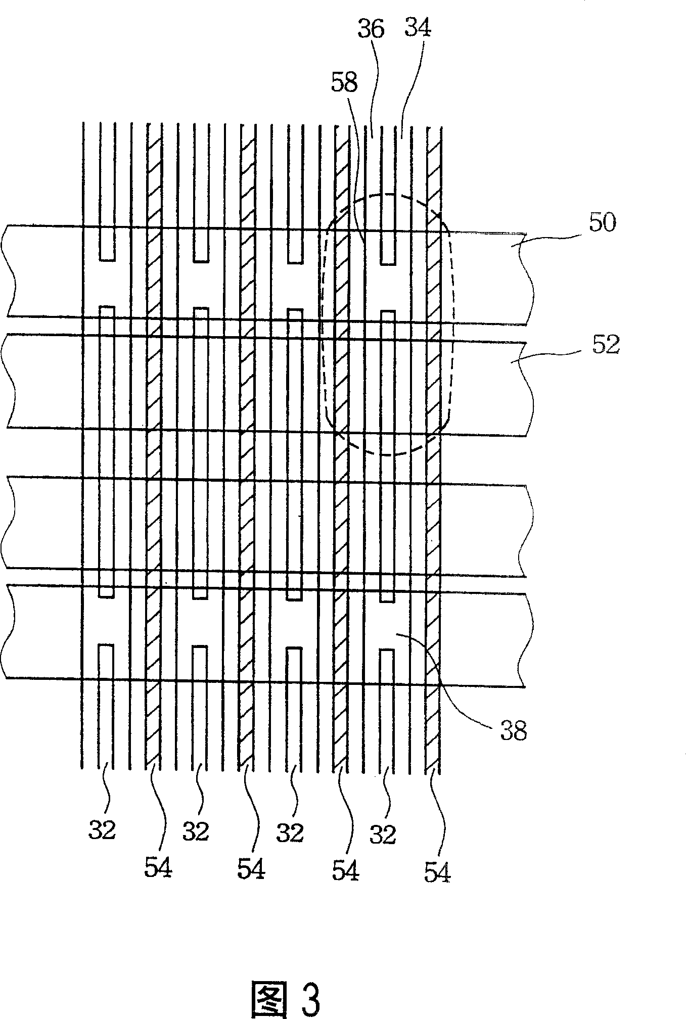
[0029] Without limiting the spirit and scope of application of the present invention, the implementation of the present invention is described below with an embodiment; those of ordinary skill in the art, after understanding the spirit of the present invention, can apply the addressing electrode of the present invention structure in various plasma displays. Each addressing electrode structure is composed of two wires, which are connected at the adjoining positions of the X electrode and the Y electrode close to the light-emitting unit, thereby increasing the writing speed. The application of the present invention should not be limited to the preferred embodiments described below.

[0030] As shown in FIG. 1 , it is a schematic top view of an address electrode structure of a plasma flat panel display according to a preferred embodiment of the present invention. The addressing electrode structure 30 of the present invention adopts the design of two wires, that is, each addressi...


PUM


Abstract

The plasma panel display at least includes upper base plate, lower base plate and multiple lightening units. Each lightening unit is controlled by X electrode, Y electrode on upper base plate and addressing electrode on lower base plate. The characters are that the structure of addressing electrode includes at least two paralleled conducting wires on lower base plate, and multiple conducting regional block located between said two parallel conducting wires utilized to coupe the parallel conducting wires. Each conducting regional block located on lower base plate corresponding to adjoining spot between X electrode and Y electrode. Advantages of the structure are: raised current tolerance of electrode and avoiding too large load at writing end.

Description

technical field [0001] The present invention relates to a plasma flat panel display (PDP), and more particularly to an address electrode structure which can improve the writing speed of light-emitting units. Background technique [0002] Due to the rapid development of multimedia, users have higher and higher requirements for peripheral sound and light equipment. The commonly used cathode ray tube or video tube (Cathode Ray Tube, CRT) type display is too bulky, and it is no longer sufficient in today's era of light, thin, short, and small. Therefore, many flat panel display technologies have been developed successively in recent years, such as liquid crystal display (Liquid Crystal Display, LCD), plasma flat panel display (Plasma Display Panel, PDP), and field emission display (Field Emission Display, FED), which have gradually become The mainstream of future displays. Among them, a plasma flat panel display (PDP) has attracted great attention as a full-color display devic...

Claims


Application Information

Patent Timeline
Patent Type & Authority Patents(China)
IPC IPC(8): H01J17/49H01J11/02H01J17/04
Inventor 高旭彬林志光徐有亿周众望
Owner CHUNGHWA PICTURE TUBES LTD
Why Eureka
Try Eureka