
Precipitation pneumatically supported serial composite solid-liquid separator

A technology of solid-liquid separation and series combination, which is applied in the direction of sedimentation separation, solid separation, separation methods, etc., can solve the problem of large floor area, easy breakage of flocs, and the inability of a single solid-liquid separation device to adapt to changes in source water quality, etc. question

Inactive Publication Date: 2006-07-19
HARBIN INST OF TECH
View PDF0 Cites 0 Cited by
  • Summary
  • Abstract
  • Description
  • Claims
  • Application Information

AI Technical Summary

Problems solved by technology

[0003] In order to solve the problem that a single solid-liquid separation device cannot adapt to the change of source water quality, in order to overcome the large area occupied by the combined use of the existing advection sedimentation and air flotation solid-liquid separation devices, the poor connection between the sedimentation and air flotation tanks leads to sedimentation The flocs in the pool float up, and the small flocs in the water entering the air flotation tank are easily broken. When the turbidity of the source water is high, the quality of the air bubbles in the air flotation process is not good, which affects the effective adhesion of the air bubbles and the flocs. The invention provides a A sedimentation air flotation series combined solid-liquid separation device
It solves the problem that a single solid-liquid separation device cannot adapt to the change of source water quality, and improves the effect of solid-liquid separation of source water

Method used


Image

  • Precipitation pneumatically supported serial composite solid-liquid separator
  • Precipitation pneumatically supported serial composite solid-liquid separator
  • Precipitation pneumatically supported serial composite solid-liquid separator

Examples


specific Embodiment approach 1

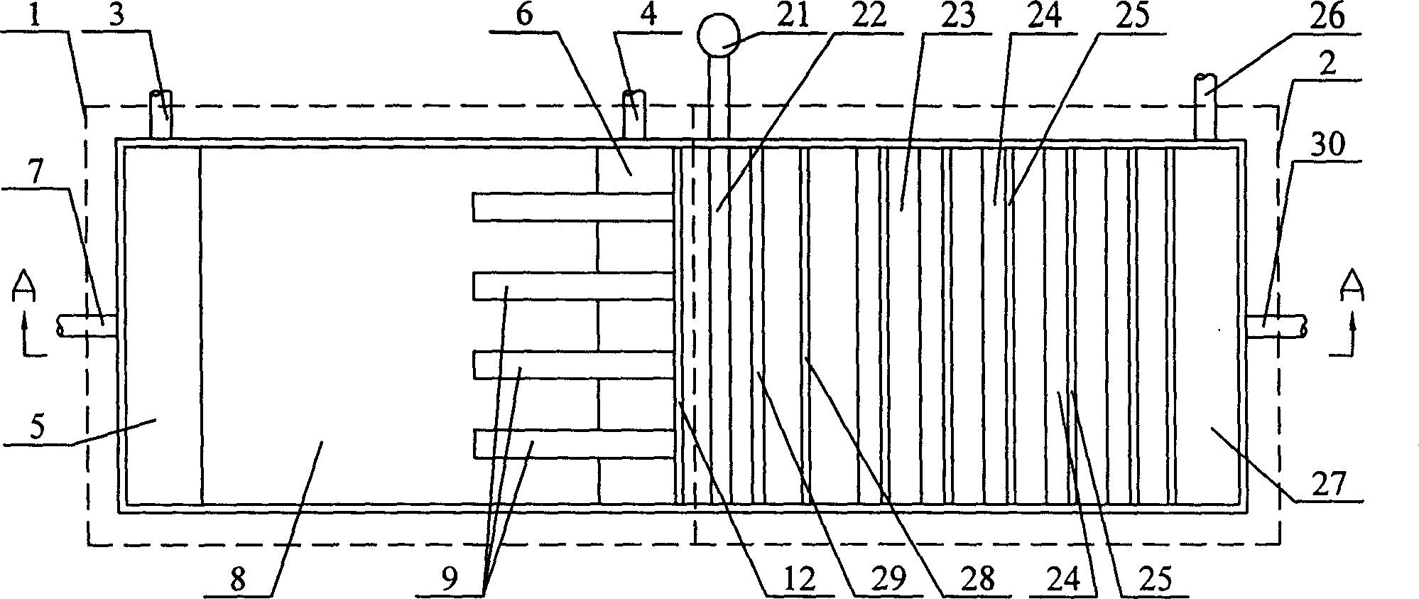
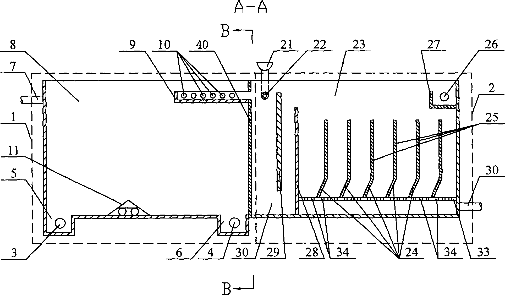
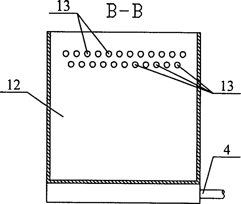
[0005] Specific implementation mode one: (see Figure 1 ~ Figure 3 ) This embodiment is made up of precipitation solid-liquid separation device 1 and air flotation solid-liquid separation device 2, and precipitation solid-liquid separation device 1 is connected in series with air flotation solid-liquid separation device 2, and precipitation solid-liquid separation device 1 is composed of sedimentation tank 8, water inlet Channel 7, perforated flower wall 12, No. 1 sludge tank 5, No. 1 slag outlet 3, No. 2 sludge tank 6, and No. 2 slag outlet 4; the water inlet channel 7 is set on the water inlet side of the sedimentation tank 8 , the perforated flower wall 12 is located on the water outlet side of the sedimentation tank 8, the perforated flower wall 12 has a water outlet hole 13, the No. 1 sludge tank 5 is located at the bottom of the water inlet side of the sedimentation tank 8, and the No. 1 slag outlet 3 is located at On the outer wall of the sedimentation tank 8 at the No....

specific Embodiment approach 2

[0006] Specific implementation mode two: (see figure 1 , figure 2 ) The difference between this embodiment and the specific embodiment one is that the first mixing plate 29, the second mixing plate 28, the perforated pipe 22 and the high-level medicine box or the dosing pump 21 are added in the air flotation tank 23, and the first mixing plate 29 is fixed on the water inlet side in the air flotation pool 23, the lower end of the first mixing plate 29 and the bottom surface of the air flotation pool 23 leave a water space 30, and the second mixing plate 28 is fixed in the air flotation pool 23 close to the first mixing plate 29 on the water outlet side, the lower end of the second mixing plate 28 is sealed and connected with the bottom surface of the air flotation pool 23, the height of the upper end of the second mixing plate 28 is lower than the height of the upper end of the first mixing plate 29, and the first mixing plate 29 and the perforated flower wall The upper part ...

specific Embodiment approach 3

[0007] Specific implementation mode three: (see figure 2 ) The difference between this embodiment and the specific embodiment one is that the perforated flower wall 12 and the water outlet hole 13 are replaced by the water collecting tank 9 and the retaining wall 40, the retaining wall 40 is fixed on the water outlet side of the sedimentation tank 8, and the water collecting tank 9 is fixed on the sedimentation tank. On the top of the retaining wall 40 on one side of the pool 8, the water collecting tank 9 has a through hole 10, the water collecting tank 9 is vertically arranged with the retaining wall 40, and one end of the water collecting tank 9 is fixed on the retaining wall 40, and communicates with the air flotation pool 23 . Other compositions and connections are the same as in the first embodiment. The effect of this embodiment is to make the water outlet of the sedimentation tank 8 uniform, which is conducive to improving the treatment effect of the air flotation ta...


PUM


Abstract

The invention relates to a kind of solid-liquid separating apparatus by tandem connection of sediment and air floating. It is a combinatorial solid-liquid separating apparatus, which involves something used in dealing with daily life drink water, municipal sewage water and industrial wastewater. The invention contains sediment solid-liquid separating apparatus (1) and air floating solid-liquid separating apparatus (2), and the sedimentation apparatus (1) and air floating apparatus (2) is with tandem connecting. Punched tracery wall (12) is set in side of water outlet in sedimentation tank, in the top of which has an osculum. The invention connects the sedimentation tank and air floating tank effectively through the punched tracery wall (12), which can save areas; in the air floating tank, there are a oblique plate, a stand plate and a gully hole plate, which are helpful to generate laminar flow in the air floating tank; and it intensifies solid-liquid separating function in the air floating tank, reduces the amount of small bubble contained in water of the air floating tank, and declines the bubble-choking possibility that generating in the filtrated bed. This invention can resolve the problems that unitary solid-liquid separating apparatus can't adapt to the change of water quantity in the water source, so it can also improve the effectiveness of solid-liquid separation in water source.

Description

Technical field: [0001] The invention relates to a combined solid-liquid separation device for domestic drinking water, municipal sewage and industrial waste water treatment. Background technique: [0002] Most of the drinking water sources in my country are surface water, and the quality of surface water is very complicated. The characteristics of source water quality in different seasons are high turbidity, high algae, low temperature and low turbidity, etc. Therefore, it is difficult to adapt to changes in water quality conditions in different seasons by using a single solid-liquid separation device. Advective sedimentation and air flotation are widely used as conventional solid-liquid separation devices in my country, but there are still the following problems: (1) The sedimentation solid-liquid separation device is suitable for the treatment of low-temperature, low-turbidity water, high-algae water, and high-color water. The effect is very poor, because the low-tempera...

Claims


Application Information

Patent Timeline
Patent Type & Authority Patents(China)
IPC IPC(8): B01D21/00B03D1/00
Inventor 马军刘芳王静超
Owner HARBIN INST OF TECH
Learn More