
Masseur

A shell and head technology, applied in the field of massage devices, can solve problems such as inability to be used by people at will, inability to perform even massage, etc.

Inactive Publication Date: 2004-10-13
MATSUSHITA ELECTRIC WORKS LTD
View PDF1 Cites 0 Cited by
  • Summary
  • Abstract
  • Description
  • Claims
  • Application Information

AI Technical Summary

Problems solved by technology

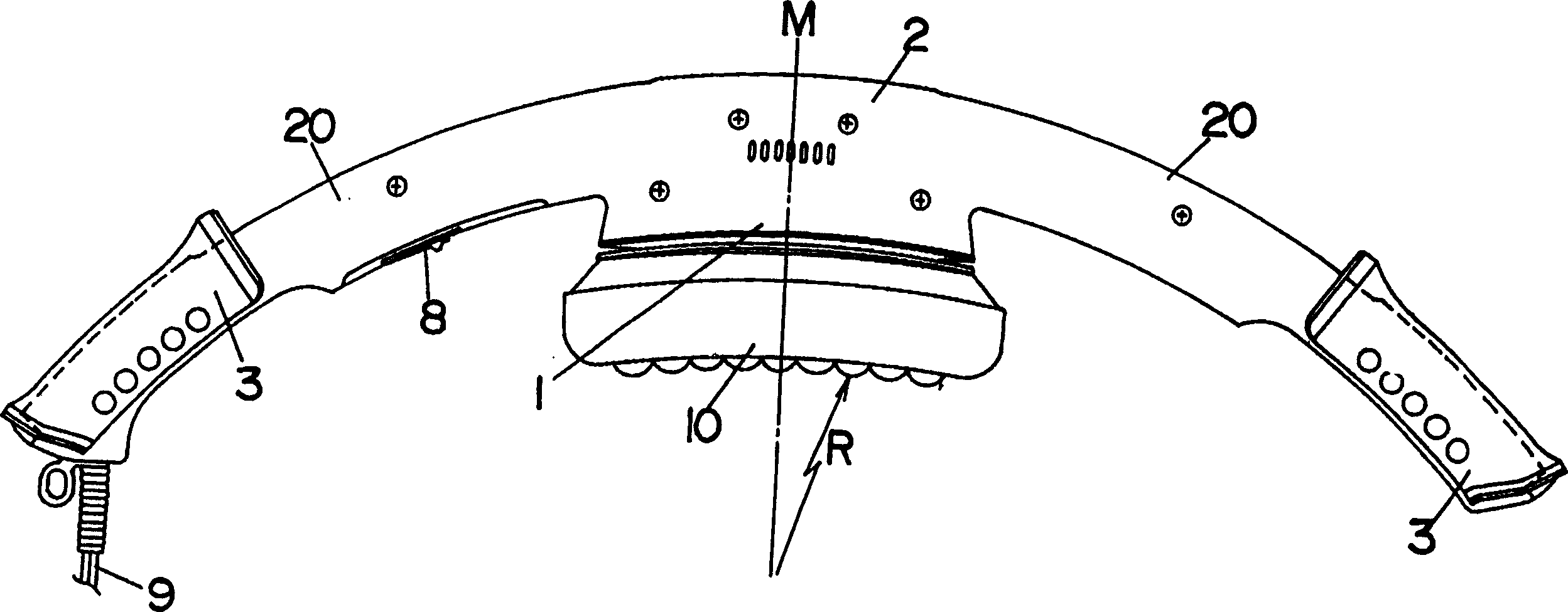
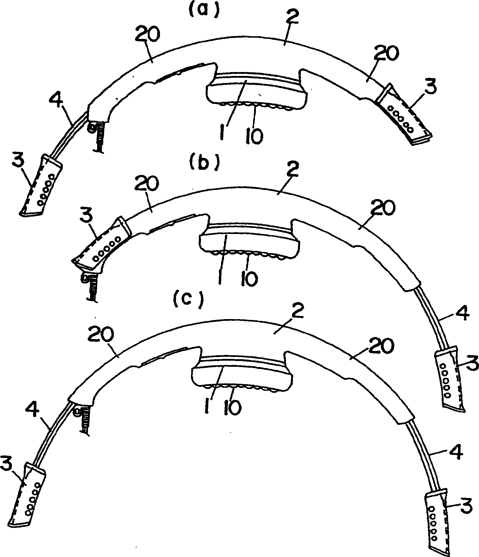
[0005] However, on the massage machine with the above-mentioned arm portion 4, since the rigidity (elasticity) of the housing 2 and the arm portion 4 are different, it is difficult for the treatment portion 10 of the head 1 to be properly placed on the back and waist, and it is impossible to perform a uniform massage. Massage, so it can't be used casually

Method used


Image

  • Masseur
  • Masseur
  • Masseur

Examples


Embodiment Construction

[0032] The present invention will be described in detail below with reference to the embodiments shown in the accompanying drawings.

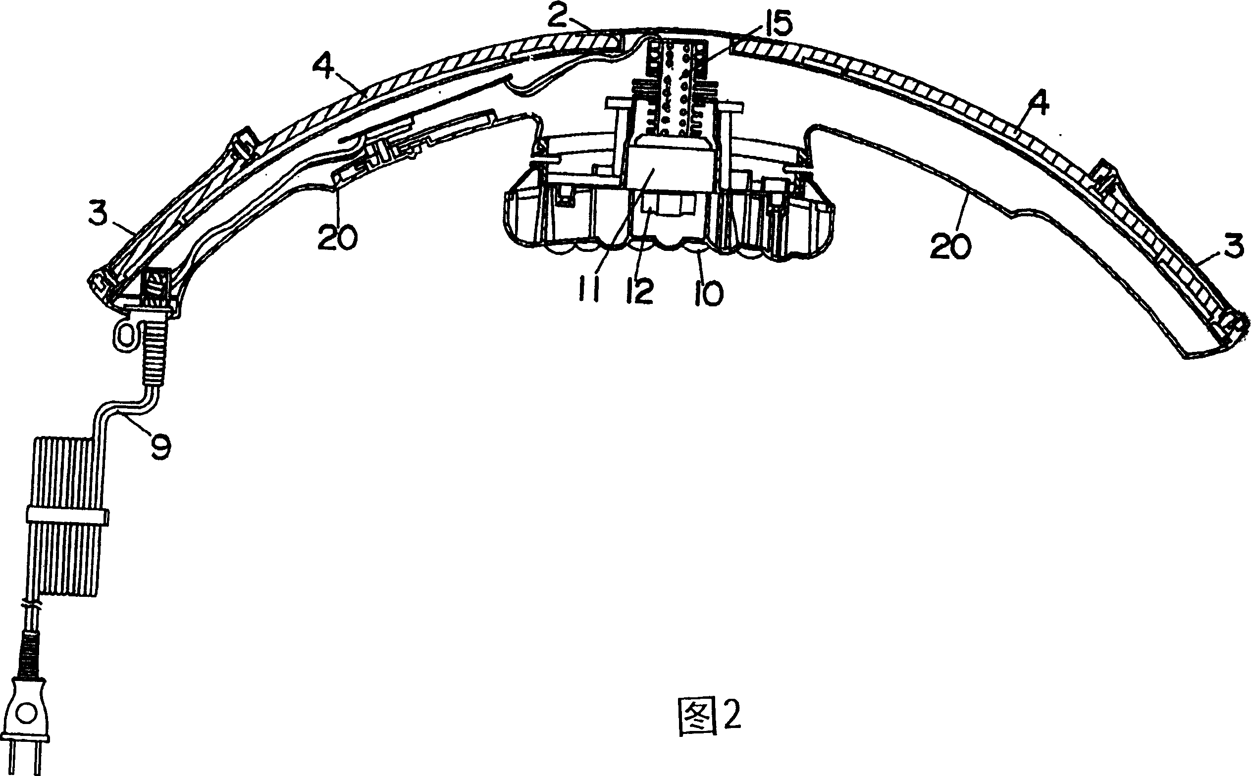
[0033] refer to figure 1 And Fig. 2, the massage machine of the present invention comprises the head 1 of built-in massage device, is provided with the treatment part 10 that contacts with human body affected part, for example, forms with elastic materials such as rubber. Further, arc-shaped casings 20 made of hard synthetic resin extend to the left and right of the head 1 , and handles 3 are disposed on the ends of the casings 20 . In the figure, the shell of the head 1 and the two shells 20 are formed on the integral shell 2 .

[0034] The above-mentioned massage device is composed of a motor 11 fixed on the head 1 by an elastic body 15 and an eccentric weight 12 fixed on the output shaft of the motor 11. Therefore, when the treatment part 10 is in contact with the affected part of the human body, If the motor 11 is driven, the vibration ca...


PUM


Abstract

A massaging apparatus is enable a massager to easily and suitably massage the shoulder and the neckincluding a head unit, a pair of housings and a pair of arms. The head unit is configured to massage a body of a user. The pair of housings are connected to opposite sides of the head unit respectively and extend in opposite directions from the head unit. The pair of arms are configured to be held by the user and provided to the pair of housings respectively.

Description

[technical field] [0001] The invention relates to a massage device. [Background technique] [0002] A kind of hand-held massager is disclosed on Japanese patent publication No. 5-20730. Such a massager is composed of a stick with a finger-pressing part in the middle and a belt attached to one end of the stick. When people want to massage their back, they hold the belt with one hand and the stick without a stick with the other hand. The other end is used to determine the position of the acupressure part on the treatment surface, and exert force on the belt and stick for massage. [0003] In such a massager, since the belt can rotate freely relative to the stick, it is difficult to accurately determine the position of the acupressure part in the middle of the stick on the treatment area. In addition, if force is applied to the belt and stick for massage, use The force on the treatment part is easy to make the acupressure part slide away from the treatment part, especially wh...

Claims


Application Information

Patent Timeline
IPC IPC(8): A61H23/02
CPCA61H23/0263A61H2205/081A61H23/02
Inventor 成濑晴彦桥本浩一
Owner MATSUSHITA ELECTRIC WORKS LTD
Learn More