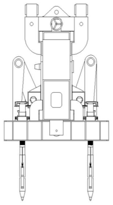
Unmanned grabbing segmental beam lifting appliance and construction method thereof

A segmental beam and spreader technology, which is applied in the direction of load hanging components, transportation and packaging, etc., can solve the problems of high safety risks, large deflection of segmental beams, and large number of construction personnel, so as to improve alignment speed and accuracy The effect of achieving stability, restraint and detachment, and improving construction convenience

Pending Publication Date: 2022-08-09
CCCC SECOND HARBOR ENG +1
View PDF0 Cites 0 Cited by
  • Summary
  • Abstract
  • Description
  • Claims
  • Application Information

AI Technical Summary

Problems solved by technology

However, for segmental beams with larger tonnage and longer width, when the four-point hoisting is used, the local load of each stress point is relatively large, and the support stiffness is small, which will cause a large deflection of the segmental beam during hoisting. It is easy to cause different degrees of damage to the segmental beam body structure
[0004] In addition, the traditional segmental beam needs to go through multiple transfers and stacking from the prefabricated beam yard to the construction site and then to the installation position of the designated segment, which means that the segmental beam needs to go through many times in the process from production to use. There are problems such as cumbersome hoisting process, large number of construction personnel required, high labor cost, long hoisting cycle, long duration of the whole process, easy damage to the body structure, and high safety risks.

Method used


Image

  • Unmanned grabbing segmental beam lifting appliance and construction method thereof
  • Unmanned grabbing segmental beam lifting appliance and construction method thereof
  • Unmanned grabbing segmental beam lifting appliance and construction method thereof

Examples


Embodiment Construction

[0071] The present invention will be further described in detail below with reference to the accompanying drawings, so that those skilled in the art can implement it with reference to the description.

[0072] It should be noted that the experimental methods described in the following embodiments are conventional methods unless otherwise specified, and the reagents and materials can be obtained from commercial sources unless otherwise specified; in the description of the present invention, The terms "landscape", "portrait", "top", "bottom", "front", "rear", "left", "right", "vertical", "horizontal", "top", "bottom", The orientation or positional relationship indicated by "inside" and "outside" is based on the orientation or positional relationship shown in the accompanying drawings, which is only for the convenience of describing the present invention and simplifying the description, and does not indicate or imply that the indicated device or element must have The particular o...


PUM


Abstract

The invention discloses an unmanned grabbing segmental beam lifting appliance and a construction method thereof. The unmanned grabbing segmental beam lifting appliance comprises a lifting beam; the distribution beam is arranged right below the hoisting beam in parallel; the transverse moving mechanisms are arranged at the bottom of the distribution beam at intervals, and any transverse moving mechanism slides in the length direction of the distribution beam; the longitudinal moving mechanisms are arranged on the corresponding transverse moving mechanisms at intervals, and any longitudinal moving mechanism slides in the width direction of the distribution beam; the plurality of padlock hanging rods are respectively connected with the plurality of longitudinal moving mechanisms, and any padlock hanging rod is used for automatically locking the segmental beam hanging hole; contact wheels of the multiple sets of auxiliary alignment devices press the side walls of the segmental beams inwards from the two sides. The hoisting stability is guaranteed through cooperation of the distribution beam and the multi-point hoisting structure, rapid alignment adjustment of the padlock hoisting rod and a segmental beam hoisting hole is achieved through cooperation of the transverse moving mechanism, the longitudinal moving mechanism and the auxiliary alignment device, the padlock hoisting rod and the segmental beam can be automatically locked or unlocked, the manual operation amount is greatly reduced, and the hoisting efficiency is improved. And the hoisting efficiency and the hoisting quality are improved.

Description

technical field [0001] The invention relates to the technical field of segment beam lifting and handling. More specifically, the present invention relates to an unmanned grabbing segment beam spreader and a construction method thereof. Background technique [0002] In the prefabrication and assembly of concrete segmental beams, the position of the lifting holes of the segmental beams is affected by a variety of factors, and the distribution is quite different. The hangers are generally in the form of end anchors installed at the ends of the finished threaded steel bars. When the hangers are used, the construction personnel need to manually adjust the distance between the hangers to adapt to the distance between the lifting holes of the segment beams. , the adjustment process requires the assistance of multiple people and cannot be adjusted in place at one time; the construction personnel are required to stand on the top surface of the segment beam to push the segment beam s...

Claims


Application Information

Patent Timeline
IPC IPC(8): B66C1/10B66C1/44B66C13/16B66C13/04
CPCB66C1/10B66C1/44B66C13/16B66C13/04
Inventor 张鸿张永涛杨秀礼夏熙陈鸣崔洪谱程茂林肖浩纪晓宇肖林郭万中曾广彬易飞冷志坚张晓平夏昊董奇峰范晨阳朱明清
Owner CCCC SECOND HARBOR ENG
Why Eureka
Try Eureka