
Segmented adjustable pressure reducing valve

A technology of pressure reducing valve and pressure reducing valve core, applied in the field of pressure reducing valve, can solve problems such as troublesome adjustment of pressure reducing valve, and achieve the effect of improving reliability, maintaining normal performance and convenient operation

Inactive Publication Date: 2022-08-02
中山市福润德燃气具有限公司
View PDF0 Cites 0 Cited by
  • Summary
  • Abstract
  • Description
  • Claims
  • Application Information

AI Technical Summary

Problems solved by technology

[0002] At present, the existing pressure reducing valve includes a valve body, a valve cover, a pressure spring, a pressure reducing valve core assembly and a pressure regulating device, wherein the pressure reducing valve core assembly generally includes a valve membrane and a lever, and the pressure regulating device is connected to the pressure regulating device through a pressure spring. The valve diaphragm is used to adjust the elastic force of the pressure spring acting on the valve diaphragm assembly. The pressure adjustment device is generally a screw adjustment mechanism. By rotating the screw, the compression degree of the pressure spring is adjusted to achieve the purpose of adjusting the elastic force. However, in actual use , the adjustment of the existing pressure reducing valve is troublesome, and special tools are needed to turn the screw

Method used


Image

  • Segmented adjustable pressure reducing valve
  • Segmented adjustable pressure reducing valve
  • Segmented adjustable pressure reducing valve

Examples


Embodiment Construction

[0030] Embodiments of the present invention are described in detail below, examples of which are illustrated in the accompanying drawings, wherein the same or similar reference numerals refer to the same or similar elements or elements having the same or similar functions throughout. The embodiments described below with reference to the accompanying drawings are exemplary, only used to explain the present invention, and should not be construed as a limitation of the present invention.

[0031] In the description of the present invention, it should be understood that the azimuth description, such as the azimuth or position relationship indicated by up, down, front, rear, left, right, etc., is based on the azimuth or position relationship shown in the drawings, only In order to facilitate the description of the present invention and simplify the description, it is not indicated or implied that the indicated device or element must have a particular orientation, be constructed and ...


PUM


Abstract

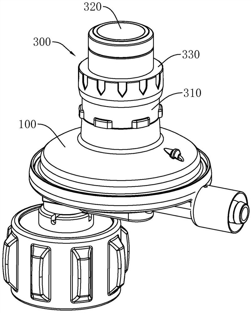
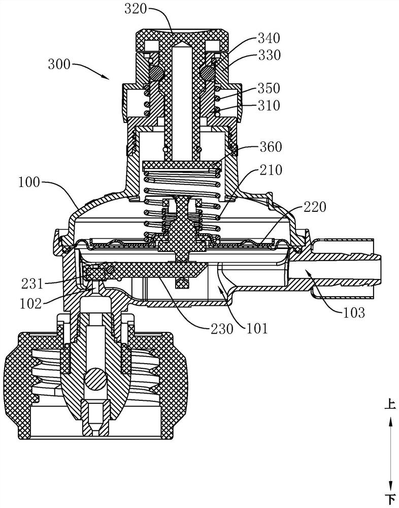
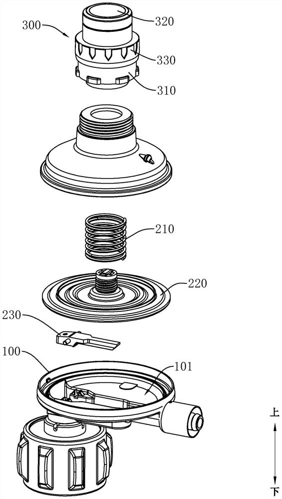
The segmented adjustable pressure reducing valve comprises a valve body, a pressure reducing valve element assembly and a pressure adjusting assembly, a valve cavity is formed in the valve body, the pressure reducing valve element assembly is arranged in the valve cavity, and the pressure reducing valve element assembly is provided with a pressure spring used for adjusting output pressure; the pressure adjusting assembly comprises a pressure adjusting seat, a key and a sliding piece, the pressure adjusting seat is installed on the valve body, the key and the sliding piece are arranged on the pressure adjusting seat in a sliding mode, the pressure spring abuts against the key, the key is provided with at least one clamping position, the pressure adjusting seat is movably provided with a locking piece corresponding to the clamping position, and the sliding piece is provided with an abutting-pushing structure and an avoiding structure which correspond to the locking piece. The sliding piece can slide to the abutting and pushing structure to correspond to the locking piece in position, and the abutting and pushing structure limits the locking piece to slide out of the clamping position. The sliding piece can slide to the avoiding structure to correspond to the locking piece in position, the avoiding structure can avoid the locking piece so that the locking piece can slide out of the clamping position, the output pressure of the pressure reducing valve can be adjusted by operating the key and the sliding piece, and operation is convenient and fast.

Description

technical field [0001] The invention relates to a pressure reducing valve, in particular to a segmental adjustable pressure reducing valve. Background technique [0002] At present, the existing pressure reducing valve includes a valve body, a valve cover, a pressure spring, a pressure reducing valve core assembly and a pressure regulating device, wherein the pressure reducing valve core assembly generally includes a valve membrane and a lever member, and the pressure regulating device is connected to the pressure regulating device through the pressure spring. The valve diaphragm is used to adjust the elastic force of the pressure spring acting on the valve diaphragm assembly. The pressure adjustment device is generally a screw adjustment mechanism. By rotating the screw, the compression degree of the pressure spring is adjusted to achieve the purpose of adjusting the elastic force. However, in actual use , the adjustment of the existing pressure reducing valve is more troub...

Claims


Application Information

Patent Timeline
Patent Type & Authority Applications(China)
IPC IPC(8): F16K1/00F16K1/32F16K17/30F16K17/34F16K27/02F16K31/126F16K31/44F16K31/60
CPCF16K1/00F16K1/32F16K17/30F16K17/34F16K27/02F16K31/1264F16K31/44F16K31/60Y02T10/30
Inventor 李华登
Owner 中山市福润德燃气具有限公司
Learn More