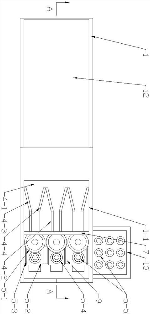
Badminton ball collecting device
A collection device, badminton technology, applied to ball games, sports accessories, etc., can solve problems such as time-consuming and labor-intensive, bad waist and legs
- Summary
- Abstract
- Description
- Claims
- Application Information
AI Technical Summary
Problems solved by technology
Method used
Image
Examples
Embodiment 1
[0051] see Figure 1-Figure 3 , the present embodiment 1 includes a casing 1 and a universal wheel 2; the casing 1 is an open bottom structure, and the four corners of the bottom of the casing 1 are connected with the universal wheel 2 through shafts and bearings, and the universal wheel 2 is provided with a driving device;
[0052] It also contains:
[0053] The transmission mechanism 3, the transmission mechanism 3 is arranged on the left side of the casing 1, and the left side wall of the casing 1 is inclined from low to high from left to right;
[0054] The sorting mechanism 4, the sorting mechanism 4 is located on the right side of the shell 1, the right side of the front and rear side walls of the shell 1 are provided with a gap 1-1, and the upper end of the right side wall of the shell 1 and the lower end of the gap 1-1 flush setting;
[0055] Collecting mechanism 5, the quantity of described collecting mechanism 5 is three, and is arranged under sorting mechanism 4; ...
Embodiment 2
[0059] see Figure 4-Figure 5 , on the basis of Embodiment 1, the transfer mechanism 3 includes:
[0060] The connection roller 3-1, the number of the connection roller 3-1 is three, and they are arranged in a slope from left to right from low to high; The connecting roller 3-1 is exposed under the casing 1; the front and rear ends of the connecting roller 3-1 are screwed to the front and rear side walls of the casing 1 through shafts and bearings respectively, and the three connecting rollers 3-1 are connected by gears and chains Transmission connection and drive by motor;
[0061] Shaving 3-2, said shaving 3-2 is respectively arranged on the ring wall of connecting roller 3-1;
[0062] The No. 1 guide plate 3-3, the No. 1 guide plate 3-3 is located at the bottom right of the connecting roller 3-1, and the No. 1 guide plate 3-3 is inclined from left to right from low to high;
[0063] No. 1 conveyor 3-4, the No. 1 conveyor 3-4 is located on the upper right side of the No. ...
Embodiment 3
[0069] see Figure 3-Figure 4 , on the basis of embodiment 2, a No. 1 connecting rod 7 is provided between the gap 1-1 of the housing 1, and the front and rear ends of the No. 1 connecting rod 7 are respectively fixed to the front and rear inner walls of the housing 1 by bolts; Picking mechanism 4 includes:
[0070] No. 2 conveyor 4-1, the No. 2 conveyor 4-1 is located on the right side of No. 1 conveyor 3-4, and is located under the right end of No. 1 conveyor 3-4; No. 2 conveyor 4-1 Connected to an external power supply, the specific model of the No. 2 conveyor 4-1 is purchased, installed and used directly from the market according to the actual use requirements;
[0071] No. 2 guide plate 4-2, the quantity of described No. 2 guide plate 4-2 is six, and is fixed on No. 1 connecting rod 7 lower ends by bolt respectively, the bottom of No. 2 guide plate 4-2 and No. 2 conveyor 4- The upper watchband of 1 is set against movement; six No. 2 guide plates 4-2 are set in pairs, an...
PUM
 Abstract
Description
Claims
Application Information
 - R&D
- Intellectual Property
- Life Sciences
- Materials
- Tech Scout
- Unparalleled Data Quality
- Higher Quality Content
- 60% Fewer Hallucinations
Browse by: Latest US Patents, China's latest patents, Technical Efficacy Thesaurus, Application Domain, Technology Topic, Popular Technical Reports.
© 2025 PatSnap. All rights reserved.Legal|Privacy policy|Modern Slavery Act Transparency Statement|Sitemap|About US| Contact US: help@patsnap.com


