
Charging terminal, equipment, system, station, energy storage pack and charging control method

A technology for charging terminals and terminal controllers, applied in the fields of charging terminals, energy storage packs and charging control, equipment, stations, and systems, can solve the problems of large transformation, high cost, and unsatisfactory social and economic benefits, and achieve Low cost, easy popularization, and high feasibility

Pending Publication Date: 2022-04-15
QINGDAO TELD NEW ENERGY TECH CO LTD
View PDF6 Cites 0 Cited by
  • Summary
  • Abstract
  • Description
  • Claims
  • Application Information

AI Technical Summary

Problems solved by technology

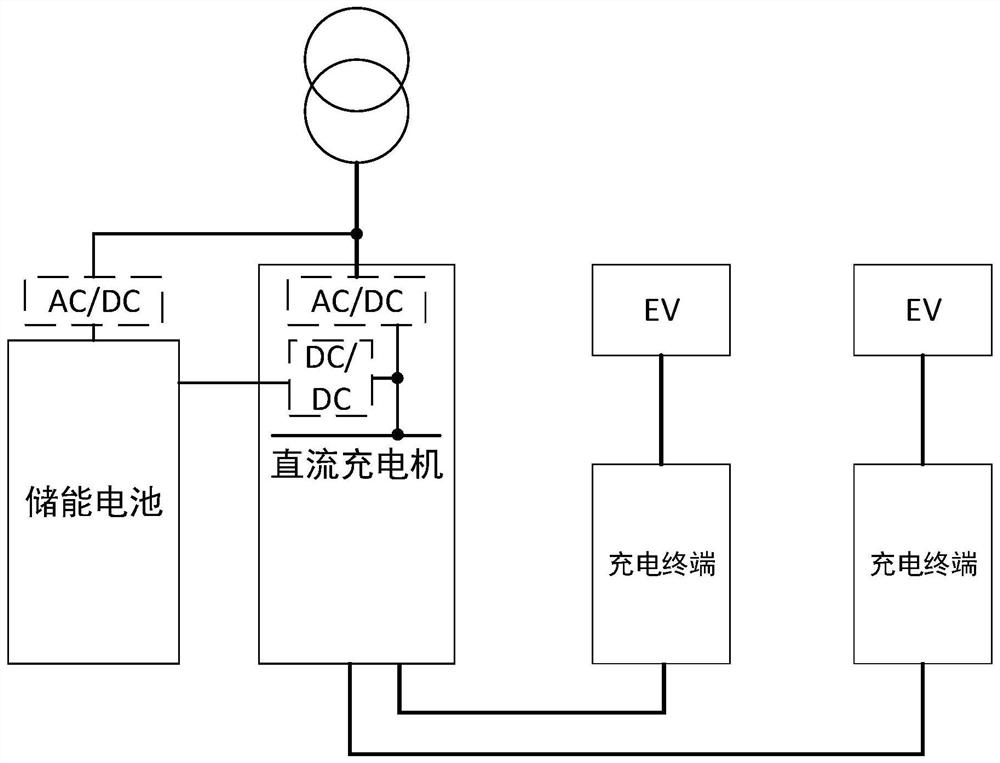
However, the setting of this integrated energy storage requires the addition of AC / DC modules, DC / DC modules and corresponding charge and discharge controls, which requires a large degree of transformation of the existing charging system, high cost, and unsatisfactory social and economic benefits.

Method used


Image

  • Charging terminal, equipment, system, station, energy storage pack and charging control method
  • Charging terminal, equipment, system, station, energy storage pack and charging control method
  • Charging terminal, equipment, system, station, energy storage pack and charging control method

Examples


Embodiment Construction

[0041] In order to make the purpose, technical solutions and advantages of the embodiments of the present invention clearer, the technical solutions in the embodiments of the present invention will be clearly and completely described below in conjunction with the drawings in the embodiments of the present invention. Obviously, the described embodiments It is a part of embodiments of the present invention, but not all embodiments. Based on the embodiments of the present invention, all other embodiments obtained by persons of ordinary skill in the art without making creative efforts belong to the protection scope of the present invention.

[0042] Please refer to Figure 4 , Figure 4 It is a schematic structural diagram of a charging terminal provided by an embodiment of the present invention. The charging terminal may include:

[0043] The first charging circuit 11 is used to transfer the electric energy output by the charger to the vehicle through the charging electrodes, ...


PUM


Abstract

The invention discloses a charging terminal, equipment, a system, a station, an energy storage pack and a charging control method, and the charging terminal comprises a first charging circuit which is used for transmitting the electric energy outputted by a charger to a vehicle through a charging electrode, and charging the vehicle; the second charging circuit is used for transmitting the electric energy output by the energy storage pack to the vehicle through the charging electrode; a terminal controller and a communication circuit; wherein the terminal controller is respectively connected with the charger and the energy storage bag through the communication circuit, and is used for controlling the charger to output electric energy to supply power to the vehicle and / or the energy storage bag according to a communication signal; according to the invention, through the arrangement of the second charging circuit and the communication circuit in the charging terminal, the existing centralized integrated energy storage aiming at the charger is adjusted into the distributed energy storage aiming at the charging terminal, the energy storage function of the charging system can be realized by slightly transforming the existing charging terminal, the feasibility is high, the cost is low, and the popularization is easy.

Description

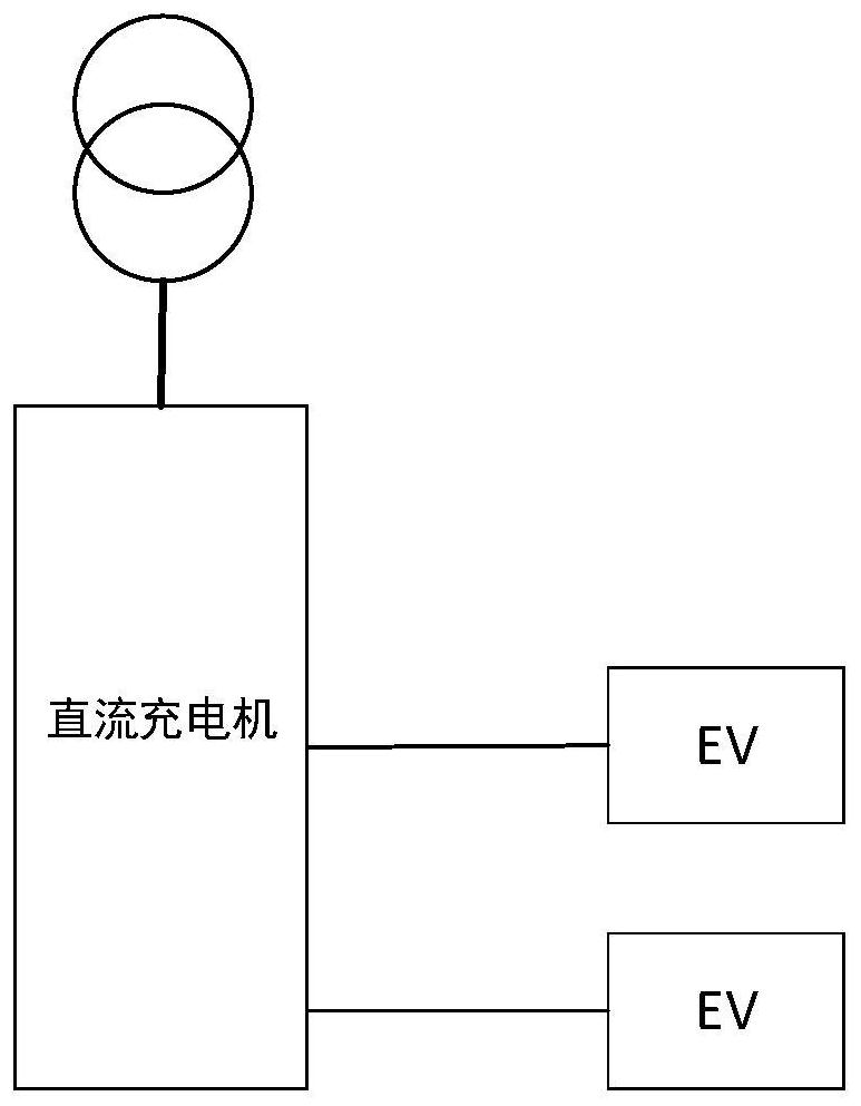
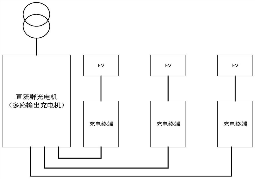
technical field [0001] The present invention relates to the technical field of charging, in particular to a charging terminal, equipment, system, station, energy storage pack and charging control method. Background technique [0002] At present, the charging system of electric vehicles often adopts such as figure 1 All-in-one charger shown, or as figure 2 The shown multi-terminal split charger charges an electric vehicle. [0003] In the prior art, in order to increase the energy storage function of the charging system, a centralized integrated energy storage is often used, such as image 3 As shown, the energy storage battery uses the AC / DC module (that is, the AC / DC conversion module) to obtain power from the grid for charging, and for discharging, the DC / DC module is used to charge the electric vehicle (EV) through the charger. However, the setting of this integrated energy storage requires the addition of AC / DC modules, DC / DC modules and corresponding charge and disc...

Claims


Application Information

Patent Timeline
Patent Type & Authority Applications(China)
IPC IPC(8): B60L53/14B60L53/16B60L53/30B60L53/53
CPCY02T10/70Y02T10/7072Y02T90/12Y02T90/14Y02T90/16
Inventor 穆晓鹏徐威栗文涛夏修龙路文刚毛宗龙王冰
Owner QINGDAO TELD NEW ENERGY TECH CO LTD
Learn More