
Brushless motor with built-in drive

A technology of motors and sliding plates, which is applied in the direction of electromechanical devices, electric components, casings/covers/supports, etc., and can solve problems such as motors are prone to vibration

Pending Publication Date: 2022-03-25
无锡市世源电机有限公司
View PDF1 Cites 0 Cited by
  • Summary
  • Abstract
  • Description
  • Claims
  • Application Information

AI Technical Summary

Problems solved by technology

[0005] In order to improve the problem of easy vibration during the working process of the motor, the application provides a brushless motor with built-in drive

Method used


Image

  • Brushless motor with built-in drive
  • Brushless motor with built-in drive
  • Brushless motor with built-in drive

Examples


Embodiment Construction

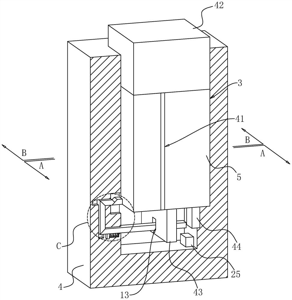
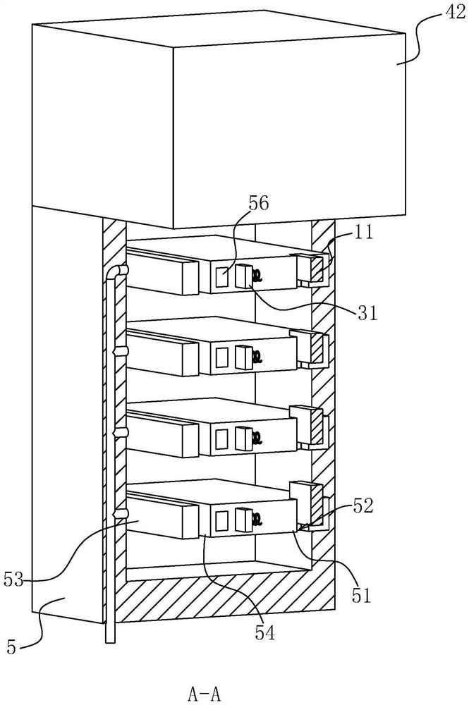
[0037] The following is attached Figure 1-7 The application is described in further detail.

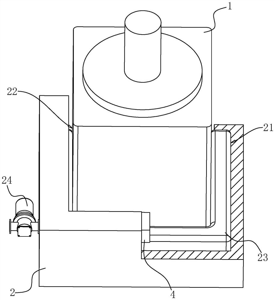
[0038] The embodiment of the present application discloses a built-in drive brushless motor. refer tofigure 1 A brushless motor with built-in drive includes a motor 1 and a base 2 arranged at the bottom of the motor 1 for fixing the motor 1 . The cross section of the base 2 is U-shaped; the base 2 is provided with a cavity 21 , and the inner peripheral surface of the base 2 is provided with a communication hole 22 communicating with the cavity 21 along its own circumference. The base 2 is fixed with an air cushion 23 through the cavity 21 . An air pump 24 is fixed on the outer peripheral surface of the base 2 , and the outlet end of the air pump 24 communicates with the inflatable cushion 23 . The base 2 provides reinforcement for the motor 1 , and when the vibration frequency of the motor 1 exceeds a preset frequency, the air pump 24 starts and inflates the air cushion 23 , so th...


PUM


Abstract

The invention relates to a brushless motor with a built-in drive, and belongs to the field of brushless motors, the brushless motor comprises a motor and a base arranged at the bottom of the motor and used for fixing the motor, a cavity is formed in the base, and a communication hole is formed in the inner circumferential surface of the base; an inflatable cushion is fixed on the base through the cavity; and an air suction pump communicated with the inflatable cushion is fixed on the peripheral surface of the base. The motor has the effect of reducing vibration in the working process of the motor.

Description

technical field [0001] The present application relates to the field of brushless motors, in particular to a built-in drive brushless motor. Background technique [0002] At present, the brushless motor is composed of the motor body and the driver. The brushless motor does not add an additional starting winding to the rotor, nor does it cause oscillation and out of step when the load changes suddenly. [0003] Related technologies can refer to the Chinese utility model patent whose authorized announcement number is CN213341925U, which discloses a brushless motor with built-in drive, including a motor body, a motor base, a circuit board and a drive board; the front of the motor base is provided with a central column , the center column is provided with a column hole through the motor base, the center column is provided with a bearing, the motor body is connected to the motor base, the rotating shaft of the motor body enters the center column through the column hole, the rotati...

Claims


Application Information

Patent Timeline
IPC IPC(8): H02K5/24H02K5/26H02K5/22
CPCH02K5/24H02K5/26H02K5/225Y02T10/64
Inventor 缪建国
Owner 无锡市世源电机有限公司
Learn More