High-performance seat for medical injection department
A high-performance, seat technology, used in hypodermic injection devices, flow control, non-electric variable control, etc., can solve problems such as potential safety hazards, inability to handle vials, boring and fatigued patient infusion, and reduce waste of resources.
- Summary
- Abstract
- Description
- Claims
- Application Information
AI Technical Summary
Problems solved by technology
Method used
Image
Examples
Embodiment 1
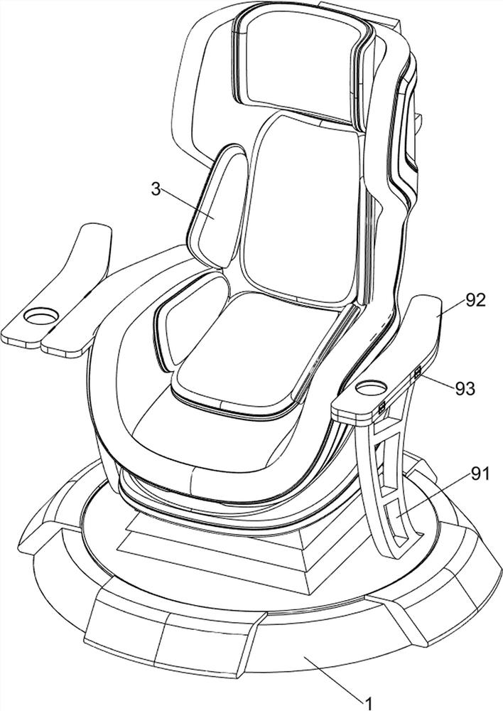
[0030] A high-performance seat for medical injection, such as Figure 1 to Figure 6 As shown, it includes a bottom plate 1, a support block 2, a seat 3, a prompting mechanism 4 and a clamping mechanism 5. The top of the bottom plate 1 is provided with a support block 2, the top of the support block 2 is provided with a seat 3, and the right side of the seat 3 is provided with a support block 2. There is a prompting mechanism 4 , and a clamping mechanism 5 is provided on the upper right side of the seat 3 .
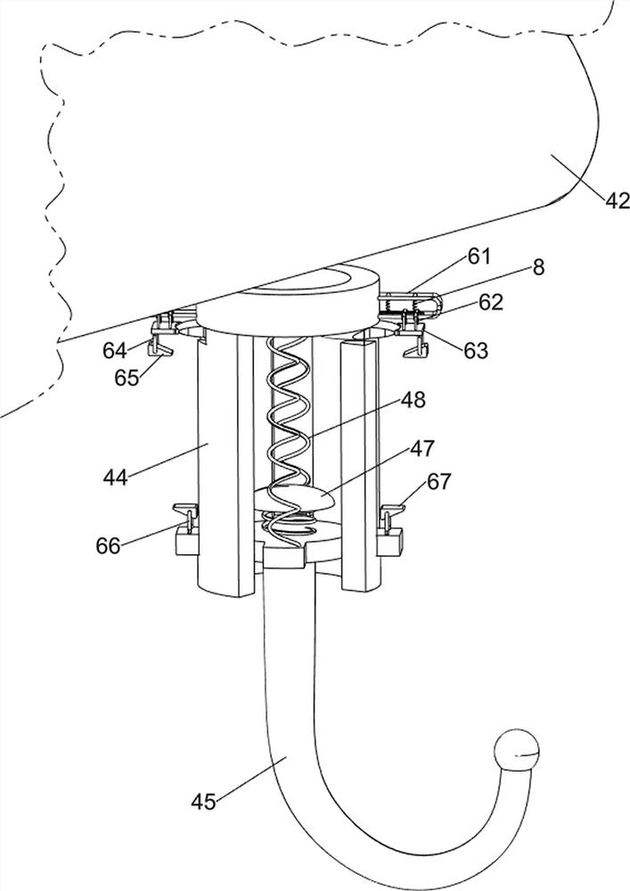
[0031] The prompting mechanism 4 includes a lifting rod 41, a turntable 42, a prompting light 43, a round tube 44, a hook 45, a first spring 46, a metal block 47 and a second spring 48. The right side of the seat 3 is slidably provided with a lifting rod 41, The top of the lift rod 41 is rotatably provided with a turntable 42, the top of the turntable 42 is provided with a prompt light 43, a plurality of round tubes 44 are arranged on the outer side of the bottom of the tu...
Embodiment 2
[0035] On the basis of Example 1, as Figure 7 and Figure 11As shown, a blocking mechanism 6 is also included, and the blocking mechanism 6 includes a guide rod 61, a sliding rod 62, an isolation plate 63, a first fixed rod 64, a first wedge-shaped block 65, a second fixed rod 66 and a second wedge-shaped Block 67, the top of the hook 45 is symmetrically provided with a second fixed rod 66, the top of the second fixed rod 66 is provided with a second wedge block 67, the upper part of the circular tube 44 is symmetrically provided with a guide rod 61, and a sliding rod is provided on the guide rod 61. 62, the bottom of the sliding rod 62 is provided with an isolation plate 63, the bottom of the isolation plate 63 is provided with a first fixed rod 64, the bottom of the first fixed rod 64 is provided with a first wedge-shaped block 65, the first wedge-shaped block 65 and the second wedge-shaped block 67 fits.
[0036] It also includes a clamping mechanism 8. The clamping mech...
Embodiment 3
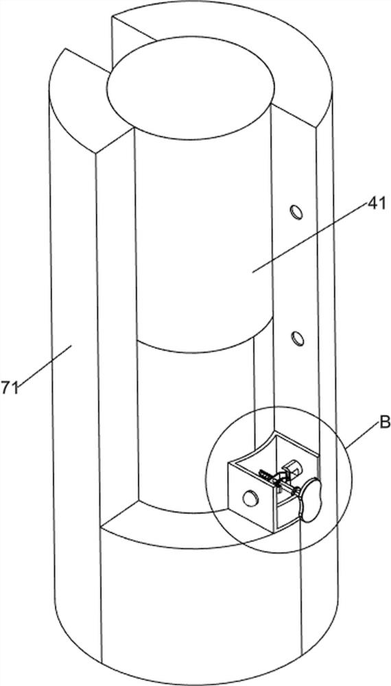
[0039] On the basis of Example 2, as Figure 8 , Figure 9 , Figure 10 and Figure 12 As shown, it also includes a lifting mechanism 7. The lifting mechanism 7 includes a sliding sleeve 71, a fixed block 72, a third fixed rod 73, a special-shaped block 74, a fourth spring 75, a clamping rod 76 and a button 77. The top right side of the bottom plate 1 A sliding sleeve 71 is provided, and the sliding sleeve 71 is slidably connected with the lifting rod 41. The lower part of the lifting rod 41 is embedded with a fixed block 72 on both sides, and the rear side of the fixed block 72 is slidably provided with a third fixing rod 73. A special-shaped block 74 is slidably arranged on the fixing rod 73 , a fourth spring 75 is connected between the rear side of the special-shaped block 74 and the third fixing rod 73 , a button 77 is arranged on the front side of the third fixing rod 73 , and the left and right sides of the fixing block 72 are Both are provided with clamping rods 76 ,...
PUM
 Abstract
Description
Claims
Application Information
 - R&D Engineer
- R&D Manager
- IP Professional
- Industry Leading Data Capabilities
- Powerful AI technology
- Patent DNA Extraction
Browse by: Latest US Patents, China's latest patents, Technical Efficacy Thesaurus, Application Domain, Technology Topic, Popular Technical Reports.
© 2024 PatSnap. All rights reserved.Legal|Privacy policy|Modern Slavery Act Transparency Statement|Sitemap|About US| Contact US: help@patsnap.com


