
Dynamic test board for needle-shaped terminal full-bridge power module

A power module and dynamic testing technology, which is applied in the direction of circuit breaker testing, measuring electricity, measuring devices, etc., can solve the problems that electrolytic capacitors and film capacitors cannot be reused, the area of ​​dynamic testing boards is large, and the cost is increased, so as to improve testing Convenience, improve test effect, improve the effect of high pressure resistance

Pending Publication Date: 2022-02-18
HUAZHONG UNIV OF SCI & TECH +1
View PDF0 Cites 2 Cited by
  • Summary
  • Abstract
  • Description
  • Claims
  • Application Information

AI Technical Summary

Problems solved by technology

In addition, the traditional dynamic test board contains large-capacity electrolytic capacitors and film capacitors, which makes the area of ​​the dynamic test board larger and the cost is higher. When changing the structure of the power module or replacing the test module, it is necessary to replace the dynamic test board. The original dynamic test The electrolytic capacitors and film capacitors on the board cannot be reused, causing a lot of waste and increasing the cost

Method used


Image

  • Dynamic test board for needle-shaped terminal full-bridge power module
  • Dynamic test board for needle-shaped terminal full-bridge power module
  • Dynamic test board for needle-shaped terminal full-bridge power module

Examples


Embodiment Construction

[0030] In order to make the object, technical solution and advantages of the present invention clearer, the present invention will be further described in detail below in conjunction with the accompanying drawings and embodiments. It should be understood that the specific embodiments described here are only used to explain the present invention, not to limit the present invention. In addition, the technical features involved in the various embodiments of the present invention described below can be combined with each other as long as they do not constitute a conflict with each other.

[0031] In the present invention, the terms "first", "second" and the like (if any) in the present invention and drawings are used to distinguish similar objects, and are not necessarily used to describe a specific order or sequence.

[0032] The full-bridge power module is a full-bridge power electronic circuit consisting of two half-bridge branches. Each half-bridge branch is composed of upper...


PUM


Abstract

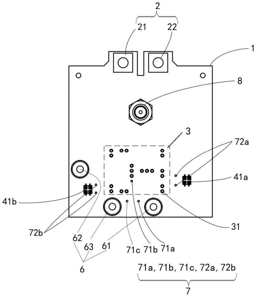
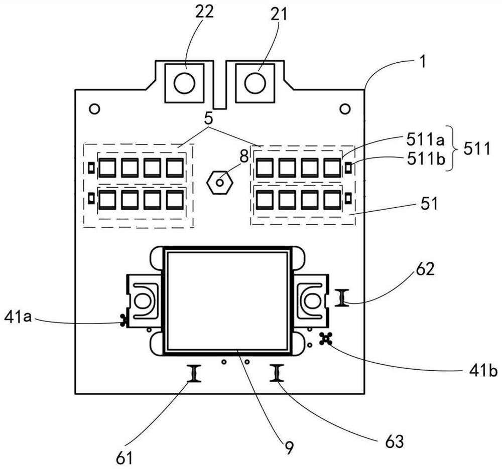
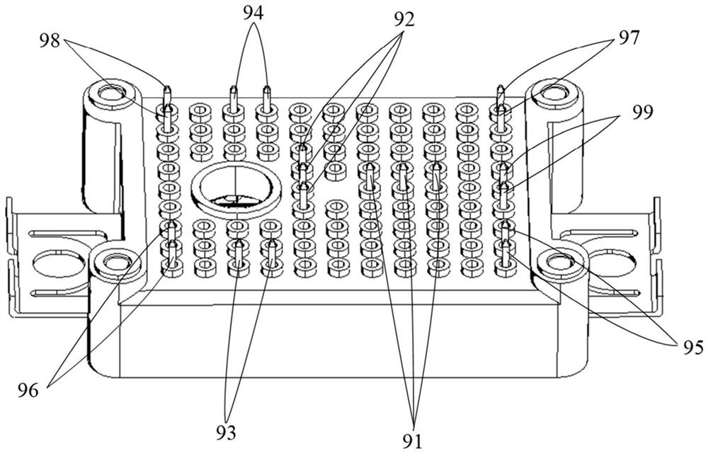
The invention discloses a dynamic test board for a needle-shaped terminal full-bridge power module, and belongs to the field of power module testing. A plurality of needle-shaped terminals are arranged on the power module, and the test board comprises a direct current bus interface, a connecting module, a driving module, a decoupling module, an inductance access module and a test module which are arranged on a double-layer circuit board; the connecting module is arranged on the outlet side of the double-layer circuit board and comprises a plurality of connecting holes in one-to-one correspondence with the needle-shaped terminals; the decoupling module is formed by connecting a plurality of decoupling branches in parallel, each decoupling branch is formed by connecting a plurality of surface-mounted decoupling capacitors in series, and the two ends of each surface-mounted decoupling capacitor are connected with a surface-mounted resistor in parallel; the decoupling module is connected with the power module plugged on the connection module, and the distance between the decoupling module and the power module is smaller than a preset threshold value; and the direct current bus interface, the driving module, the inductance access module and the test module are respectively connected with the corresponding connecting holes. The dynamic test board is small in area, low in cost, flexible to adjust and resistant to high voltage, and the test effect is improved.

Description

technical field [0001] The invention belongs to the field of power module testing, and more specifically relates to a dynamic testing board for full-bridge power modules with pin-shaped terminals. Background technique [0002] In recent years, with the development of power electronics technology, power modules using pin terminals have been greatly developed. The terminal position of the power module can be adjusted flexibly, which brings great convenience to the module design. As an important part of the full-bridge power module test, the dynamic test generally uses a double-pulse test method to test the switching performance parameters of each switching tube in a certain half-bridge. [0003] For the full-bridge power module with pin-shaped terminals, it includes two half-bridge branches, and the terminal positions are flexible and changeable. Therefore, there is a higher flexible layout requirement for the dynamic test board. In addition, the traditional dynamic test boa...

Claims


Application Information

Patent Timeline
Patent Type & Authority Applications(China)
IPC IPC(8): G01R31/00G01R31/327G01R1/30
CPCG01R31/00G01R31/327G01R1/30
Inventor 陈材吕坚玮刘新民靳洋李阳吴春瑜康勇
Owner HUAZHONG UNIV OF SCI & TECH
Learn More