


Quick Research
Generate reliable direction feasibility study reports for your R&D in just a few steps.

Technical Q&A
Discover and master advanced knowledge NOW. Basics, ideas, possibilities, all at once.

Find Solutions
As an expert in R&D theories, this can generate solutions to your technical problems instantly.

Evaluate Feasibility
Analyze your overall solution with one click, know your potential R&D risks in advance.

Monitor Landscape
Get weekly tech updates, stay abreast of the latest tech innovations and key insights.
Flush handle for vehicle door
An embedded and handle technology, which is applied in the direction of vehicle locks, lock applications, and damping devices for the movement of lock parts, can solve problems such as unsmooth operation, and achieve the effect of smooth and increased operation
- Summary
- Abstract
- Description
- Claims
- Application Information
AI Technical Summary
Problems solved by technology
Method used
Image

Examples
no. 1 example
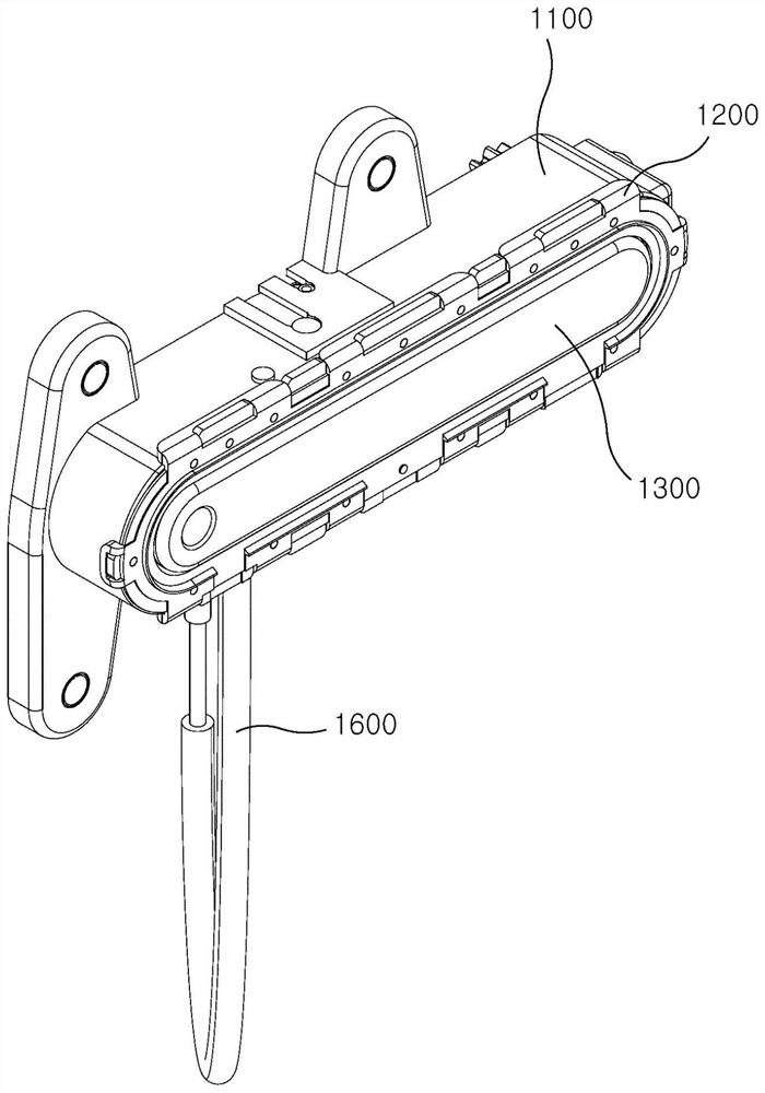
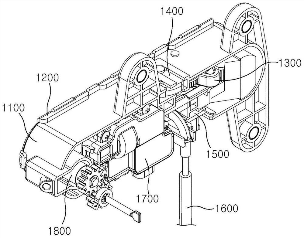
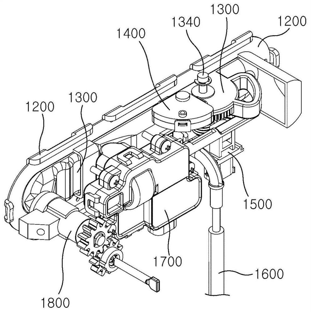
[0069] Such as Figures 1 to 3 As shown, the built-in handle for a vehicle door according to the first exemplary embodiment of the present invention includes a housing 1100 , a handle part 1300 installed in the housing 1100 , and a driving part configured to transmit power to the handle part 1300 1700.
[0070] The handle part 1300 is rotated on the rotation shaft 1340 to be drawn out or inserted through the driving part 1700 .
[0071] In the following, reference will be made to Image 6 with Figure 7 Describe each component in detail.
[0072]
[0073] exist Figure 8 with Figure 9 The housing 1100 is shown in detail in FIG.
[0074] The housing 1100 is formed to have an overall shape of a cuboid having an opened rear. That is, the case includes a front surface portion and a peripheral portion formed to protrude rearward from a periphery of the front surface portion.
[0075] A front surface portion of the housing 1100 is formed as a front plate 1110 .
[0076] ...
no. 2 example
[0571] Such as Figure 4 As shown, the built-in handle for a vehicle door according to the second exemplary embodiment of the present invention includes a housing 1100 and a handle part 1300 installed in the housing 1100 . That is, in the second embodiment, unlike the above-described first embodiment, the driving portion 1700 is not installed.
PUM
 Abstract
Description
Claims
Application Information
 - R&D Engineer
- R&D Manager
- IP Professional
- Industry Leading Data Capabilities
- Powerful AI technology
- Patent DNA Extraction
Browse by: Latest US Patents, China's latest patents, Technical Efficacy Thesaurus, Application Domain, Technology Topic, Popular Technical Reports.
© 2024 PatSnap. All rights reserved.Legal|Privacy policy|Modern Slavery Act Transparency Statement|Sitemap|About US| Contact US: help@patsnap.com