
Alarm device capable of cutting off power supply based on voltage control equipment

A technology for voltage control equipment and power cut-off, applied in alarms, mechanical equipment, instruments, etc., can solve the problems of cumbersome bolt penetration steps, inconvenient installation of alarm devices, and inability of automatic fitting and fixing of alarm devices.

Active Publication Date: 2021-11-05
江苏特力威信息系统有限公司
View PDF8 Cites 0 Cited by
  • Summary
  • Abstract
  • Description
  • Claims
  • Application Information

AI Technical Summary

Problems solved by technology

[0004] The alarm device is usually installed on the wall through the installation bracket, and the installation bracket and the alarm device are usually installed and fixed by bolts. The bolt penetration step is relatively cumbersome, which is inconvenient for the alarm device to be installed quickly, resulting in that the alarm device cannot be automatically fitted and fixed during installation.

Method used


Image

  • Alarm device capable of cutting off power supply based on voltage control equipment
  • Alarm device capable of cutting off power supply based on voltage control equipment
  • Alarm device capable of cutting off power supply based on voltage control equipment

Examples


Embodiment 1

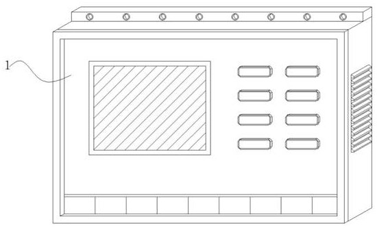
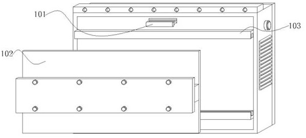
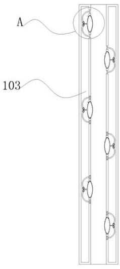
[0031] Embodiment 1: An alarm device that can cut off the power supply based on voltage control equipment, including an alarm 1, an air switch 101 is installed on the back of the alarm 1, a bracket 103 is installed through the back of the alarm 1, and a through frame is penetrated inside the bracket 103 102, the inner side of the bracket 103 is provided with a limit mechanism that can be automatically clamped;

[0032] Among them: the alarm 1 is electrically connected to the power supply through the power cord, the alarm 1 is connected to the control equipment, the air switch 101 is connected to the control equipment through the alarm 1, the air switch 101 is convenient for the alarm to cut off the power as a whole, and the bracket 103 is vertically corresponding Setting, the bracket 103 is set in a concave shape, and the inside of the bracket 103 is set in a hollow shape. When the through frame 102 is embedded in the inside of the bracket 103, the limit mechanism automatically...

Embodiment 2

[0043] Embodiment 2: with reference to instruction manual Figure 4 and 7 It can be seen that the difference between Embodiment 2 and Embodiment 1 is that the limit mechanism includes a connecting rod 4, a tooth piece 401, a swing rod 5, a gear 501 and a bump 502, the connecting rod 4 is installed on one side of the airbag 2, and the tooth The piece 401 is arranged at both ends of the connecting rod 4, the gear 501 is rotated and fitted on the outside of the tooth piece 401, the swing rod 5 swings on one end of the gear 501, and the protrusion 502 swings on one end of the swing rod 5;

[0044] The swing rod 5 is arranged in a curved shape. When the bump 502 is at rest, the bump 502 is movably nested inside the bracket 103. The bump 502 is set in a concave shape. The swing rod 5 and the gear 401 are matched to the upper and lower ends of the connecting rod 4;

[0045] Wherein: the airbag 2 drives the connecting rod 4 to slide horizontally, the connecting rod 4 drives the gear ...


PUM


Abstract

The invention provides an alarm device capable of cutting off a power supplybased on voltage control equipment. The alarm device comprises an alarm, an air switch mounted on the back of the alarm, a support mounted on the back of the alarm in a penetrating manner, a penetrating frame mounted on the inner side of the support in a penetrating manner, a limiting mechanism capable of being automatically clamped on the inner side of the support, the limiting mechanism comprises an air bag, an adsorption layer, a negative pressure valve, a sleeve, a telescopic rod, a rotating shaft and a baffle, the air bag is embedded in the support, the adsorption layer is embedded in the inner side of the air bag, the air bag drives a connecting rod to horizontally slide, the connecting rod drives gears to swing through a tooth piece, meanwhile the gears at the upper end and the lower end of the tooth piece swing at an angle, the gears rapidly drive a protruding block to swing at an angle through a swing rod, one side of the protruding block is tightly attached to the outer side of the penetrating frame, the limiting mechanism automatically and tightly limits the outer side of the penetrating frame through extrusion of the penetrating frame on the air bag, relative extrusion limiting is formed between the penetrating frame and the protruding block, and the effect that the support and the penetrating frame are automatically embedded and fastened is achieved.

Description

technical field [0001] The invention relates to the technical field of voltage control, in particular to an alarm device capable of cutting off power supply of equipment based on voltage control. Background technique [0002] The electrical control system is generally called the secondary control loop of electrical equipment. Different equipment has different control loops, and the control methods of high-voltage electrical equipment and low-voltage electrical equipment are different. The voltage control system is controlled by the control equipment, and the control equipment is in the During use, an alarm device is required to give an early warning to the control equipment to avoid failure to alarm when the voltage is too high; [0003] Aiming at the technical problems of the above-mentioned alarm device, it is found through retrieval that there is a patent No. CN202010672919.0, a voltage-sensitive alarm device and its alarm method, the voltage-sensitive alarm device and it...

Claims


Application Information

Patent Timeline
Patent Type & Authority Applications(China)
IPC IPC(8): G08B21/00F16M11/04F16B47/00
CPCG08B21/00F16M11/04F16B47/00
Inventor 陈海锋浦溯周一波
Owner 江苏特力威信息系统有限公司
Learn More