Anti-theft jewelry cabinet with display and alarm functions
A functional and jewelry technology, applied in display cabinets, anti-theft alarm mechanical activation, home appliances, etc., can solve the problems of heavy jewelry cabinets, inconvenient to move, etc.
- Summary
- Abstract
- Description
- Claims
- Application Information
AI Technical Summary
Problems solved by technology
Method used
Image
Examples
Embodiment 1
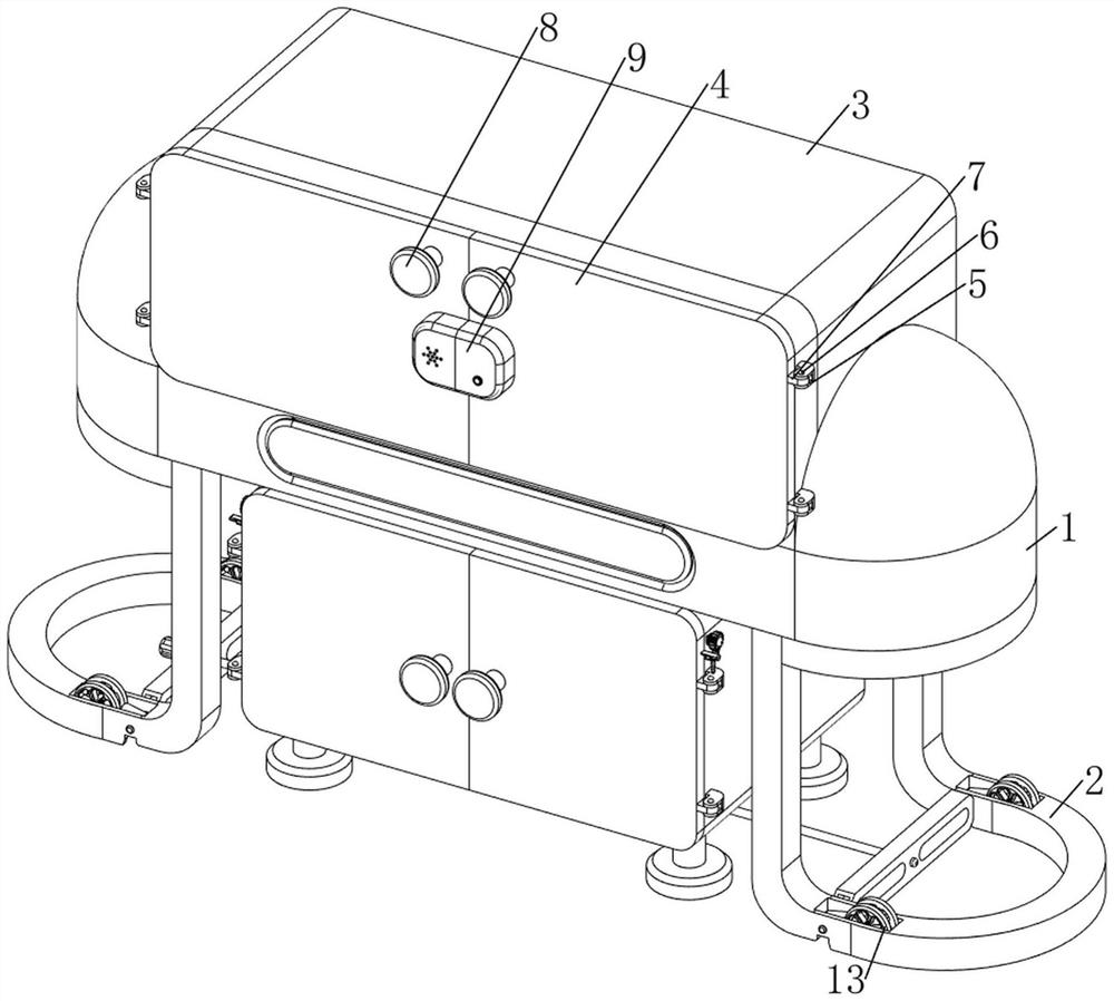
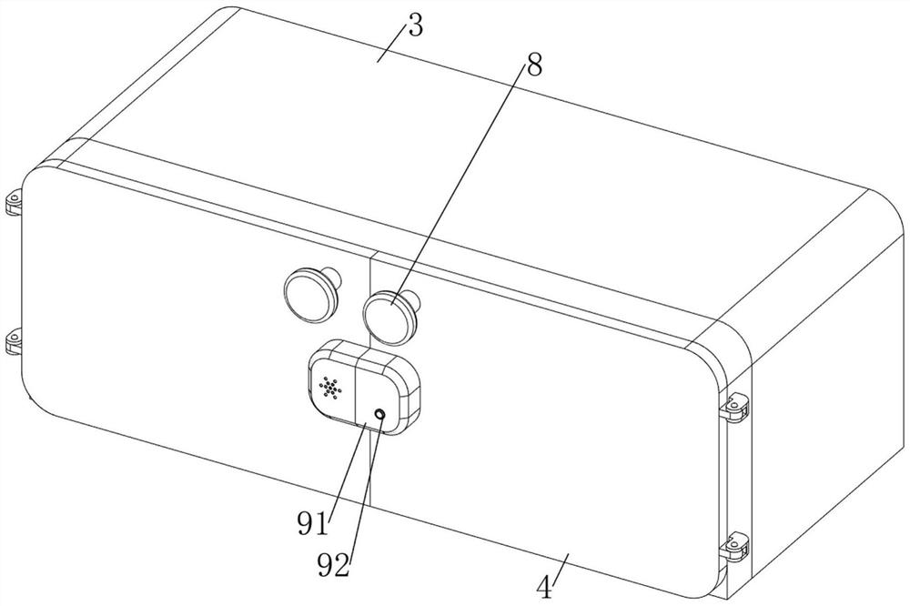
[0106] An anti-theft jewelry cabinet with display and alarm functions, such as Figure 1-Figure 7 As shown, it includes a fixed plate 1, a support frame 2, a glass baffle 3, a first movable plate 4, a first fixed block 5, a first rotating shaft 6, a second fixed block 7, a first handle 8, an anti-theft mechanism 9 and Lifting mechanism 10, support frame 2 is provided on the left and right sides of the bottom of fixed plate 1, glass baffle 3 is arranged in the middle of the top of fixed plate 1, and first fixed block 5 is arranged symmetrically up and down on the left and right sides of glass baffle 3, The front side of the first fixed block 5 is all rotatably provided with a first rotating shaft 6, and the middle part of the first rotating shaft 6 is provided with a second fixed block 7, and a first movable plate is arranged between the two second fixed blocks 7 on the same side. 4. The first movable boards 4 all block the front side of the glass baffle 3, the first handles 8 ...
Embodiment 2
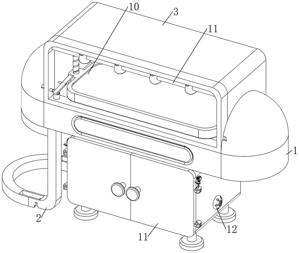
[0111] On the basis of Example 1, such as figure 2 , Figure 8 and Figure 9 As shown, the lighting mechanism 11 is also included, and the lighting mechanism 11 includes a first fixed rod 111, a lighting lamp 112, a second fixed rod 113, a fourth movable plate 114, a third housing 115, a fourth housing 116, a third spring 117, block 118, fourth spring 119 and second switch 1110, first fixed rod 111 is provided on the front upper part of the inner side of the glass baffle 3, and a plurality of lighting lamps 112 are evenly spaced on the first fixed rod 111, and the glass baffle 3. A second fixed rod 113 is provided on the left front and lower part of the inner wall, and a fourth movable plate 114 is arranged on the right side of the second fixed rod 113, and a glass baffle is provided on the left front and lower part of the inner wall. 3 The fourth shell 116 is provided on the left front side of the inner bottom, and the right part of the third shell 115 is slidingly provide...
Embodiment 3
[0114] On the basis of Example 2, such as figure 1 , figure 2 , Figure 10 , Figure 11 , Figure 12 , Figure 13 , Figure 14 , Figure 15 , Figure 16 and Figure 17 As shown, a storage mechanism 12 is also included. The storage mechanism 12 includes a frame body 121, a leg 122, a fifth fixed block 123, a second rotating shaft 124, a sixth fixed block 125, a fifth movable plate 126, a third handle 127, Storage frame 128, first rack 129, third rotating shaft 1210, second gear 1211, torsion spring 1212, third gear 1213, guide rod 1214, fifth spring 1215, clamping plate 1216 and raised plate 1217, bottom of fixed plate 1 A frame body 121 is arranged in the middle, and the left and right sides of the bottom of the frame body 121 are provided with legs 122 symmetrically. The rotary type is provided with a second rotating shaft 124, and the middle part of the second rotating shaft 124 is provided with a sixth fixed block 125, and the fifth movable plate 126 is arranged b...
PUM
 Abstract
Description
Claims
Application Information
 - R&D
- Intellectual Property
- Life Sciences
- Materials
- Tech Scout
- Unparalleled Data Quality
- Higher Quality Content
- 60% Fewer Hallucinations
Browse by: Latest US Patents, China's latest patents, Technical Efficacy Thesaurus, Application Domain, Technology Topic, Popular Technical Reports.
© 2025 PatSnap. All rights reserved.Legal|Privacy policy|Modern Slavery Act Transparency Statement|Sitemap|About US| Contact US: help@patsnap.com


