Camera control method and system and electronic equipment
A control method and technology of electronic equipment, which is applied to the parts of the TV system, TV, electrical components, etc., can solve the problem of repeated lifting and lowering of the camera, and achieve the effects of avoiding repeated lifting, fewer modules, and simple timing control
- Summary
- Abstract
- Description
- Claims
- Application Information
AI Technical Summary
Problems solved by technology
Method used
Image

Examples
Embodiment 1
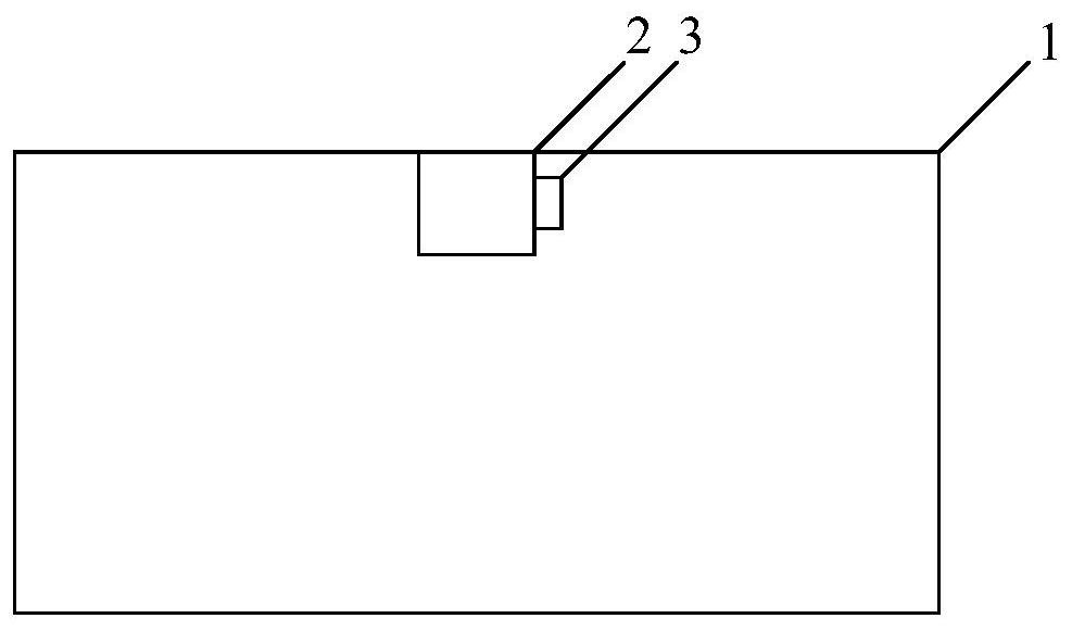
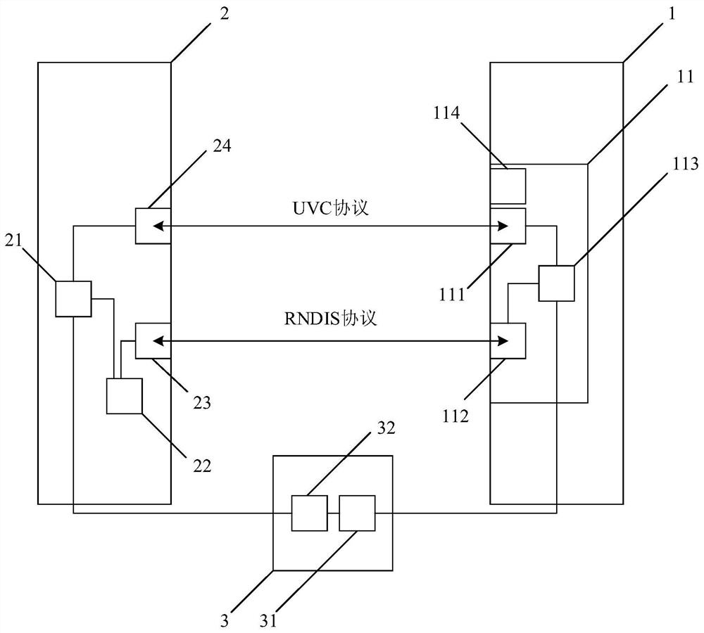
[0051] Such as figure 1 and figure 2 As shown, Embodiment 1 of the present application discloses an electronic device, which includes a display device 1 , a photographing device 2 and a lifting device 3 .
[0052] The display device 1 has a proxy module 11 , and the proxy module 11 is a camera proxy module (camera proxy module) 11 . The cameraproxy module 11 may include a control unit 111 , a sending unit 112 , a receiving unit 113 and a monitoring unit 114 . The photographing device 2 has a camera 21 , an outflow and outflow detection module 22 , an information sending module 23 and an information receiving module 24 . The lifting device 3 comprises a lift 32 controlled by a motor 31 .
[0053] The display device 1 and the camera device 2 are connected through a USB cable (Universal Serial Bus, Universal Serial Bus). The photographing device 2 is mechanically connected with the lifting device 3 .
[0054] Wherein, from the perspective of controlling the camera, the elec...
Embodiment 2
[0071] The embodiment of the present application discloses a camera control method, using the display device 1, the shooting device 2, the lifting device 3 and the multiple modules in the electronic equipment disclosed in the first embodiment of the application to control the camera. The system executes the camera control method of Embodiment 2 of the present application.
[0072] The camera control method is applied to electronic equipment. In the electronic equipment, the display device 1 is used to display images, the photographing device 2 is used to capture images through the camera 21, and the lifting device 3 is used to drive the lifting device 3 of the photographing device 2 up and down. . A long connection is maintained between the display device 1 and the shooting device 2 through the first channel; the method includes the following steps: the shooting device 2 receives the first outflow instruction triggered by the first application through the first channel or the ...
Embodiment 3
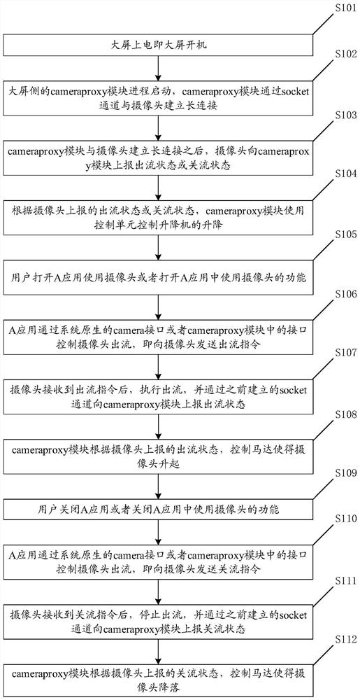
[0081] Such as image 3 As shown, the embodiment of the present application discloses a camera control method, which is formed by using the display device 1, the photographing device 2, the lifting device 3 and multiple modules in the electronic equipment disclosed in the embodiment 1 of the present application. The camera control system of the present application executes the camera control method of Embodiment 3 of the present application.
[0082] The camera control method mainly decides to control the motor to rise or fall according to the flow-out state or the flow-off state of the camera, and is specifically realized through the following steps.
[0083] S101: Power on the large screen means that the large screen is turned on.
[0084] S102: The cameraproxy module process on the side of the large screen starts, and the cameraproxy module establishes a long connection with the camera through the socket channel.
[0085] S103: After the cameraproxy module establishes a l...
PUM
 Abstract
Description
Claims
Application Information
 - R&D
- Intellectual Property
- Life Sciences
- Materials
- Tech Scout
- Unparalleled Data Quality
- Higher Quality Content
- 60% Fewer Hallucinations
Browse by: Latest US Patents, China's latest patents, Technical Efficacy Thesaurus, Application Domain, Technology Topic, Popular Technical Reports.
© 2025 PatSnap. All rights reserved.Legal|Privacy policy|Modern Slavery Act Transparency Statement|Sitemap|About US| Contact US: help@patsnap.com