


Quick Research
Generate reliable direction feasibility study reports for your R&D in just a few steps.

Technical Q&A
Discover and master advanced knowledge NOW. Basics, ideas, possibilities, all at once.

Find Solutions
As an expert in R&D theories, this can generate solutions to your technical problems instantly.

Evaluate Feasibility
Analyze your overall solution with one click, know your potential R&D risks in advance.

Monitor Landscape
Get weekly tech updates, stay abreast of the latest tech innovations and key insights.
Injection mold
An injection mold and template technology, applied in the field of injection molds, can solve the problems of low production efficiency, cumbersome mold repair and adjustment, etc., and achieve the effect of improving production efficiency and convenient mold repair and adjustment.
- Summary
- Abstract
- Description
- Claims
- Application Information
AI Technical Summary
Problems solved by technology
Method used
Image

Examples
Embodiment 1
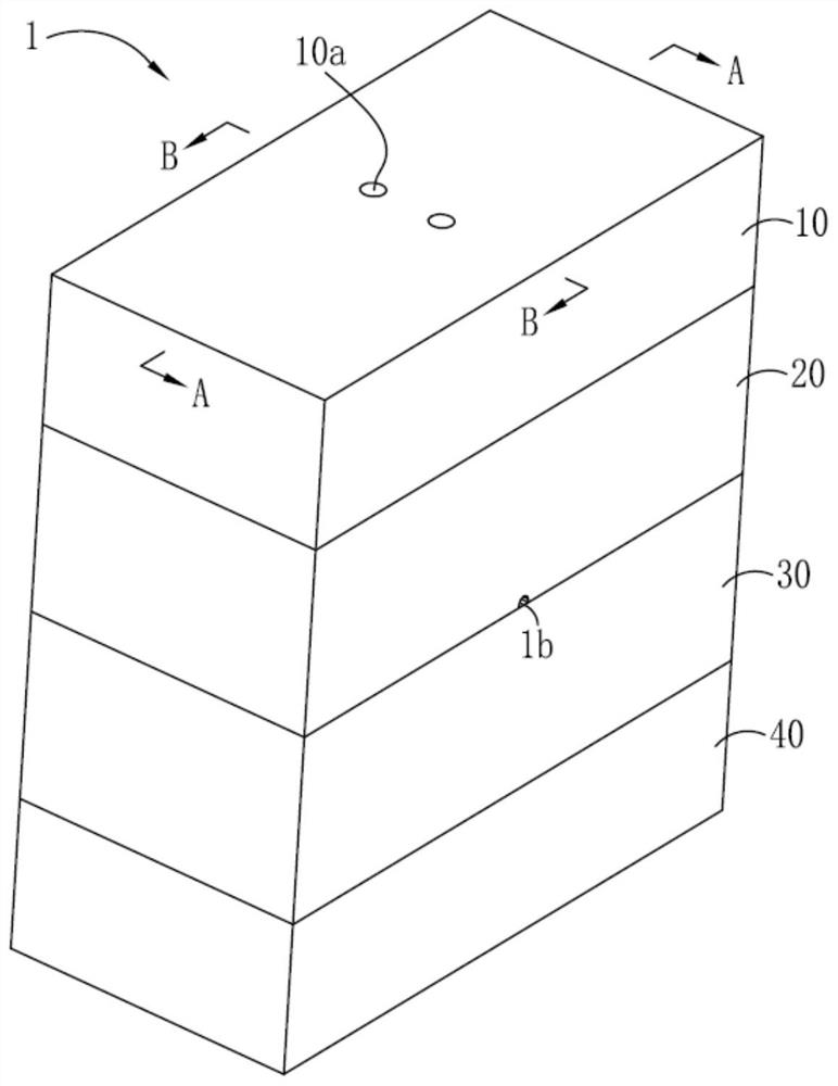
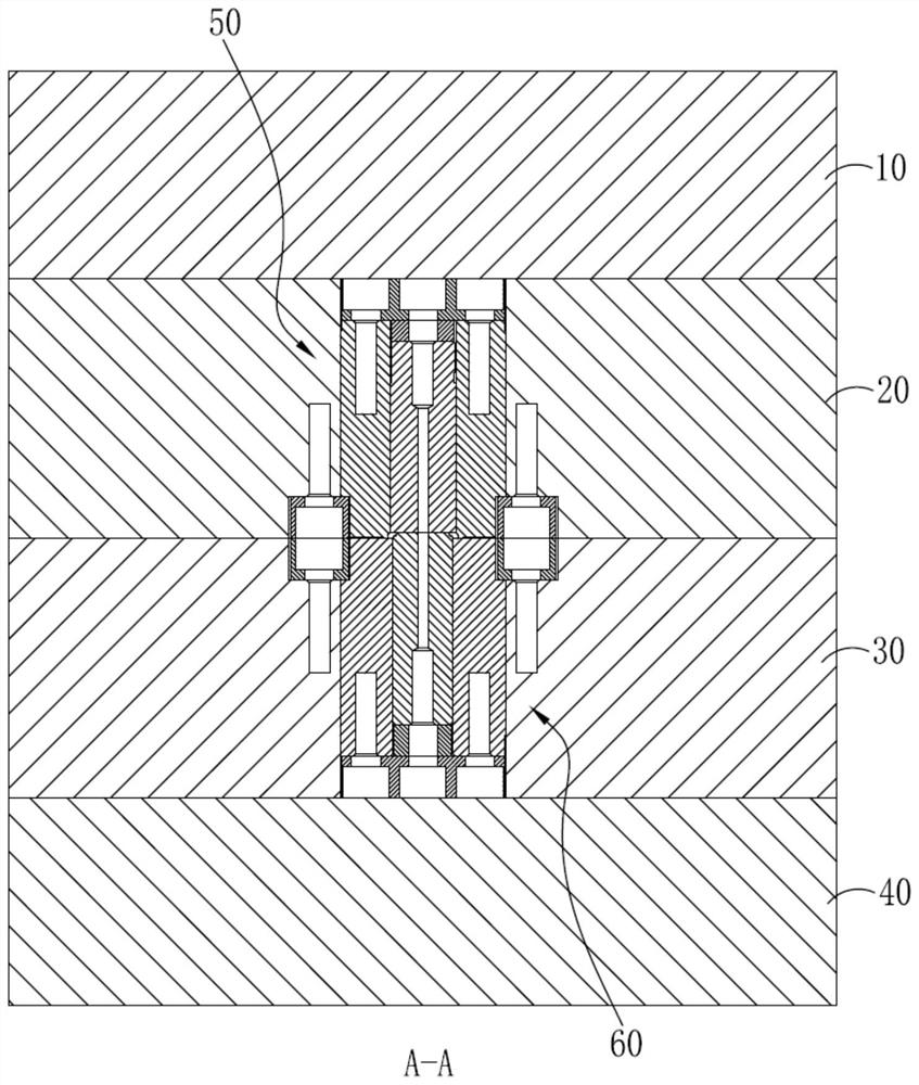
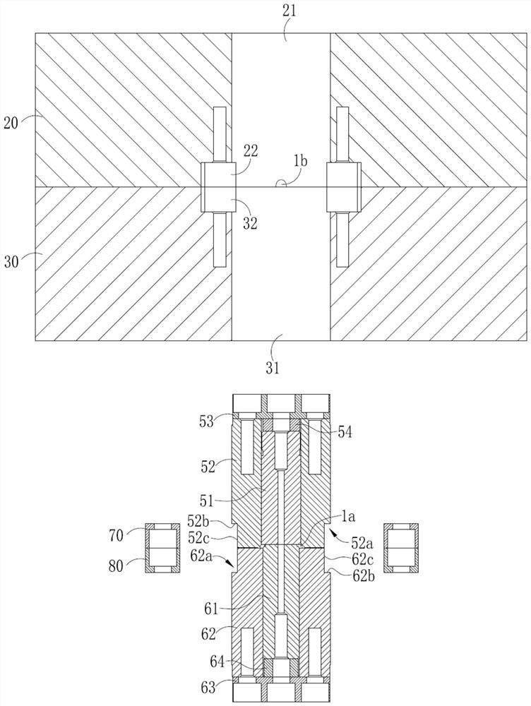
[0043] Please also refer to Figure 1 to Figure 3 , is a structural schematic diagram of an injection mold 1 provided in Embodiment 1 of the present invention. The injection mold 1 includes a first fixing plate 10, a first template 20, a second template 30, a second fixing plate 40, and a first core assembly 50. The second core assembly 60, the first pressing block 70 and the second pressing block 80, the first template 20 is set on the first fixing plate 10, and the side of the first template 20 facing away from the first fixing plate 10 is set There are a first mounting hole 21 and a first groove 22, the second template 30 is connected to the first template 20, the second template 30 is located on the side of the first template 20 away from the first fixing plate 10, the second template 30 The second template 30 is provided with a second installation hole 31 and a second groove 32 on one side facing the first template 20, and the second fixing plate 40 is arranged on the sid...
Embodiment 2
[0073] see Figure 4 , is a schematic structural diagram of a spacer 2 provided in Embodiment 2 of the present invention. The spacer 2 is used to space or compress lenses of optical lenses. The spacer 2 is made by the injection mold of Embodiment 1.
[0074] Embodiment 2 of the present invention provides a spacer 2, which is made by the injection mold of Embodiment 1. During the production process, it is more convenient to modify and adjust the mold, and the production efficiency is higher.
Embodiment 3
[0076] Embodiment 3 of the present invention provides a lens made by using the injection mold of Embodiment 1.
[0077] Embodiment 3 of the present invention provides a lens, which is made by using the injection mold of Embodiment 1. During the production process, mold repair and adjustment are more convenient and the production efficiency is higher.
PUM
 Abstract
Description
Claims
Application Information
 - R&D Engineer
- R&D Manager
- IP Professional
- Industry Leading Data Capabilities
- Powerful AI technology
- Patent DNA Extraction
Browse by: Latest US Patents, China's latest patents, Technical Efficacy Thesaurus, Application Domain, Technology Topic, Popular Technical Reports.
© 2024 PatSnap. All rights reserved.Legal|Privacy policy|Modern Slavery Act Transparency Statement|Sitemap|About US| Contact US: help@patsnap.com