Novel handle connecting seat and small agricultural machine

A technology for connecting seats and handles, which is applied in pivotal connections, mechanical equipment, sliding contact bearings, etc., can solve problems such as radial swing of mechanical parts, and achieve the effects of avoiding friction, saving processing costs, and preventing damage

Pending Publication Date: 2021-08-03
临沂市丰盈机械配件有限公司
View PDF0 Cites 0 Cited by
  • Summary
  • Abstract
  • Description
  • Claims
  • Application Information

AI Technical Summary

Problems solved by technology

[0008] In order to solve the above technical problems, the object of the present invention is to provide a new type of handle connecting seat, which prolongs the service life of the wires connected by the mechanical parts at both ends of the handle connecting seat; swing problems while reducing production costs

Method used


Image

  • Novel handle connecting seat and small agricultural machine
  • Novel handle connecting seat and small agricultural machine
  • Novel handle connecting seat and small agricultural machine

Examples


Embodiment 1

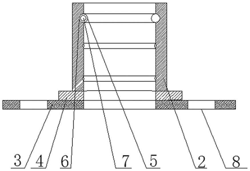
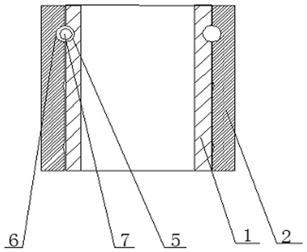
[0052] This embodiment provides a new type of handle connecting seat, which includes a lower base 3, the lower base 3 is connected with the first sleeve 1, and the lower base 3 is provided with a first through hole communicating with the first sleeve 1;

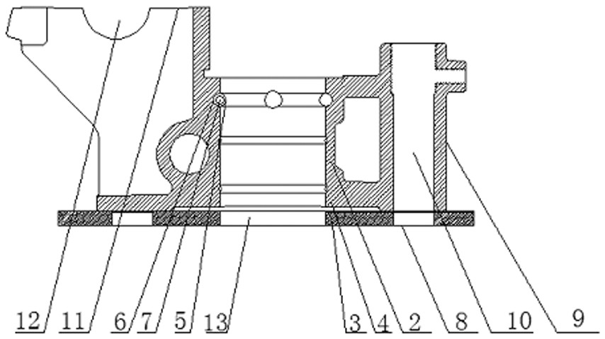
[0053] Also includes an upper base 4, the upper base 4 is connected with the second sleeve 2, the upper base 4 is provided with a second through hole 13 communicating with the second sleeve 2; the second sleeve 2 is sleeved on Outside the first sleeve 1; the second sleeve 2 is rotationally connected with the first sleeve 1, that is, the first sleeve 1 and the first sleeve 2 form a rotating shaft, and the middle of the rotating shaft is a hollow structure; the upper base 4 Mechanical parts can be connected with the lower base 3;

[0054] Also includes a limiting device, the limiting device is located between the first sleeve 1 and the second sleeve 2, not connected with the first sleeve 1 and the second sleeve 2, and the limit...

Embodiment 2

[0066] The same place of this embodiment and embodiment 1 will not be repeated;

[0067] The second limiting device includes a fixing part, the fixing part is a threaded fixing part 17, the threaded fixing part 17 is connected with the first sleeve 1, and the distance between the threaded fixing part 17 and the lower base 3 is no greater than Less than the sum of the lengths of the second sleeve 2 and the upper base 3; the threaded fixing member 17 is sleeved on the first sleeve 1 and is threadedly connected with the first sleeve 1 .

[0068] The hemispherical mounting groove 12 has a diameter of 32cm.

Embodiment 3

[0070] The same place of this embodiment and embodiment 1 will not be repeated;

[0071] The second limiting device includes a fixing member, the fixing member is an annular buckle fixing member 15, and the ring-shaped buckle fixing member 15 is sleeved on the first sleeve 1; the outer wall of the first sleeve 1 is provided with There is an annular protrusion 16 ; the annular buckle fixing part 15 is located between the end of the second sleeve 2 away from the lower base 3 and the annular protrusion 16 .

[0072] The hemispherical mounting groove 12 has a diameter of 36cm.


PUM


Abstract

The invention discloses a novel handle connecting seat which comprises a lower base, an upper base and a limiting device, the lower base is connected with a first sleeve, and the lower base is provided with a first through hole communicating with the first sleeve. The upper base is connected with a second sleeve, and the upper base is provided with a second through hole communicating with the second sleeve. The second sleeve is arranged outside the first sleeve in a sleeving manner. The second sleeve is rotationally connected with the first sleeve. The limiting device is located between the first sleeve and the second sleeve or located at the end of the second sleeve, and the limiting device makes contact with the outer wall of the first sleeve to prevent the first sleeve from axially moving relative to the second sleeve. Through the handle connecting seat, the service life of wires connected with mechanical parts at the two ends of the handle connecting seat is prolonged; and meanwhile, the problem that mechanical parts at the two ends of the handle connecting seat radially swing after the handle connecting seat is used for a certain time is solved, and the production cost is reduced.

Description

technical field [0001] The invention relates to the field of handle connecting seats, in particular to the field of handle connecting seats of small agricultural machines. Background technique [0002] The handle connection seat is used in various fields of mechanical equipment to realize the relative rotation between two mechanical parts; the bearing connection is generally used in the base of the rotating shaft, and the middle shaft of the rotating shaft is a solid shaft; this realizes the sensitive rotation of the rotating shaft. [0003] When the traditional handle connecting seat is used in the field of small agricultural machinery, due to the production environment used by small agricultural machinery, the road is uneven, and there are crops around the equipment during work, and the relative rotating mechanical parts connected at both ends of the handle connecting seat basically need wires for electrical connection , these wires can only be fixed on the surface of the ...

Claims


Application Information

Patent Timeline
Patent Type & Authority Applications(China)
IPC IPC(8): F16C11/04F16C17/02F16C33/06F16C33/10H02G3/04
CPCF16C11/04F16C17/02F16C33/06F16C33/103H02G3/04
Inventor 田立中
Owner 临沂市丰盈机械配件有限公司
Why Eureka
Try Eureka