Agricultural automatic corn threshing equipment
A corn threshing and automatic technology, applied in threshing equipment, application, agriculture, etc., can solve the problems of inconvenient collection, low work efficiency, scattered corn kernels, etc., to avoid random scattering, facilitate collection work, and high work efficiency. Effect
- Summary
- Abstract
- Description
- Claims
- Application Information
AI Technical Summary
Problems solved by technology
Method used
Image
Examples
Embodiment 1
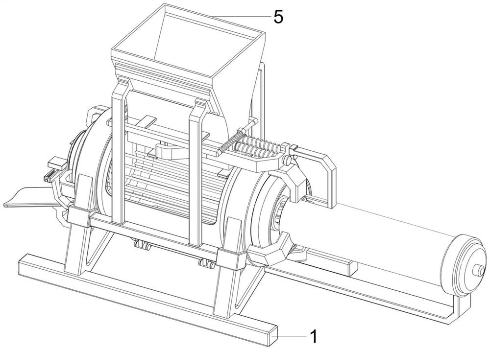
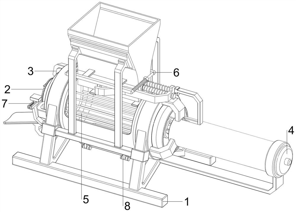
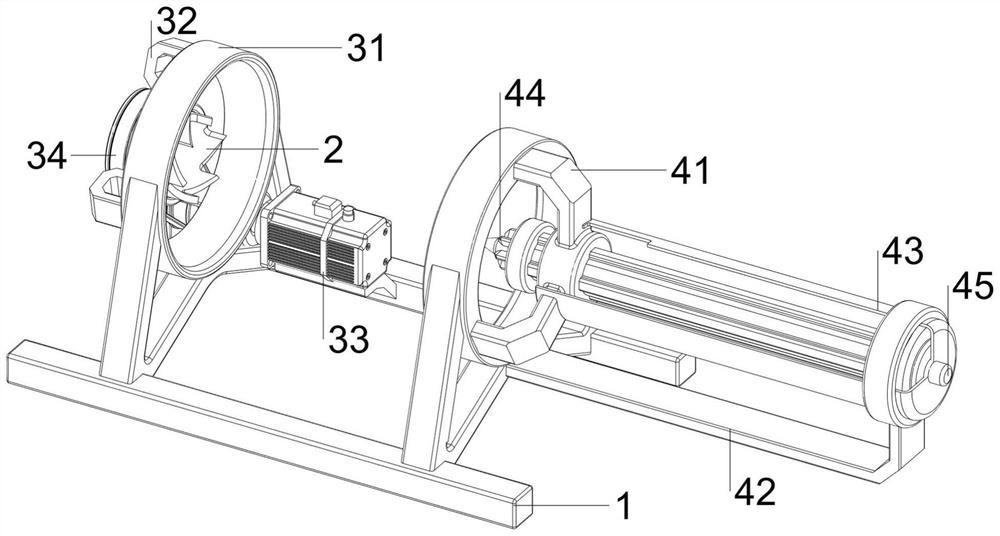
[0061] A kind of agricultural automatic corn threshing equipment, such as Figure 1-Figure 3 As shown, it includes a base 1, a runner 2, a threshing mechanism 3 and a pushing mechanism 4, and a threshing mechanism 3 is arranged between the tops of the base 1 on the front and rear sides, and the threshing mechanism 3 is rotatably provided with a runner 2, and the threshing mechanism 3 is provided with pushing mechanism 4.
[0062] The threshing mechanism 3 includes a first mounting frame 31, an axle sleeve 32, a motor 33 and a pulley assembly 34. The first mounting frame 31 is symmetrically arranged between the base 1 tops on the front and rear sides, and the first mounting frame 31 on the left side is left and right. The upper part of the side is provided with a shaft sleeve 32, and the runner 2 rotates in the shaft sleeve 32. A motor 33 is arranged on the left side of the top of the base 1 on the rear side, and a pulley assembly 34 is arranged between the output shaft of the ...
Embodiment 2
[0066] On the basis of Example 1, such as Figure 4 with Figure 5 As shown, a material storage mechanism 5 is also included, and the material storage mechanism 5 includes a fourth mounting frame 51, a material guide groove 52, a first material blocking plate 53 and a material receiving frame 54, and the front and rear symmetry between the first mounting frame 31 tops A fourth installation frame 51 is provided, and a material guide groove 52 is provided between the inner upper part of the fourth installation frame 51, and a first material blocking plate 53 is provided between the upper inner side of the first installation frame 31, and the upper inner side of the first installation frame 31 A material receiving frame 54 is arranged in between, and the material receiving frame 54 is located inside the first material blocking plate 53 , and the material receiving frame 54 is located directly below the material guide groove 52 .
[0067] Also includes a discharge mechanism 6, th...
Embodiment 3
[0070] On the basis of Example 2, such as Figure 6-Figure 8 As shown, it also includes a limit mechanism 7, and the limit mechanism 7 includes a sixth mounting frame 71, a guide rail 72, a block 73, a guide plate 74, a second guide rod 75 and a fourth spring 76, and the first mounting frame on the left side 31 The sixth installation frame 71 is arranged symmetrically front and rear on the left side lower part, and the top of the sixth installation frame 71 is provided with a guide rail 72, and the inside of the guide rail 72 is provided with a second guide rod 75, and the second guide rod 75 is provided with a sliding type. Block 73, a guide plate 74 is provided in the middle of the bottom of the first mounting bracket 31 on the left side, a fourth spring 76 is sleeved on the second guide rod 75, and the two ends of the fourth spring 76 are respectively connected with the guide rail 72 and the block 73 on the same side .
[0071] After the runner 2 threshed the corn, the eje...
PUM
 Abstract
Description
Claims
Application Information
 - R&D
- Intellectual Property
- Life Sciences
- Materials
- Tech Scout
- Unparalleled Data Quality
- Higher Quality Content
- 60% Fewer Hallucinations
Browse by: Latest US Patents, China's latest patents, Technical Efficacy Thesaurus, Application Domain, Technology Topic, Popular Technical Reports.
© 2025 PatSnap. All rights reserved.Legal|Privacy policy|Modern Slavery Act Transparency Statement|Sitemap|About US| Contact US: help@patsnap.com


