
Pulse detonation tube performance calculation method and device

A technology of pulse detonation and calculation method, applied in jet propulsion devices, rocket engine devices, ramjet engines, etc., can solve problems such as cumbersome process, high detonation frequency, heavy workload, etc., and achieve accuracy and convenience uniform effect

Pending Publication Date: 2021-07-23
AERO ENGINE ACAD OF CHINA
View PDF0 Cites 0 Cited by
  • Summary
  • Abstract
  • Description
  • Claims
  • Application Information

AI Technical Summary

Problems solved by technology

However, due to the assumption that the detonation frequency is infinite, which is inconsistent with the actual situation of a limited number of cycles, the performance obtained is relatively high
The calculation results of the characteristic diagram method are closer to the real situation, but it is necessary to calculate the thermal parameters at each moment and position, and the process of obtaining the characteristic curve is very cumbersome and the workload is huge

Method used


Image

  • Pulse detonation tube performance calculation method and device
  • Pulse detonation tube performance calculation method and device
  • Pulse detonation tube performance calculation method and device

Examples


Embodiment 1

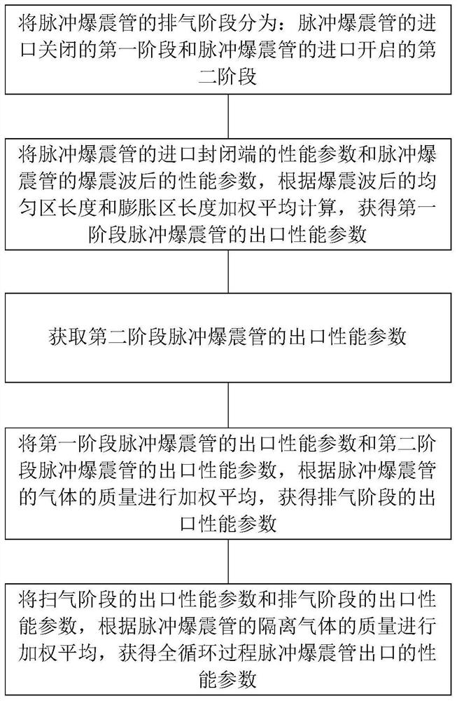
[0073] refer to figure 1 , an embodiment of the present invention provides a method for calculating the performance of a pulse detonation tube, including:

[0074] The exhaust stage of the pulse detonation tube is divided into: the first stage when the inlet of the pulse detonation tube is closed and the second stage when the inlet of the pulse detonation tube is opened;

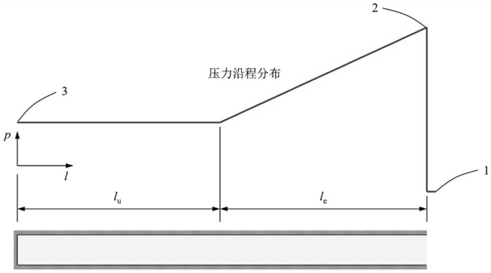
[0075] The performance parameters of the closed end of the inlet of the pulse detonation tube and the performance parameters of the pulse detonation tube after the detonation wave are calculated according to the weighted average of the length of the uniform zone and the length of the expansion zone after the detonation wave to obtain the outlet of the first stage pulse detonation tube performance parameters;

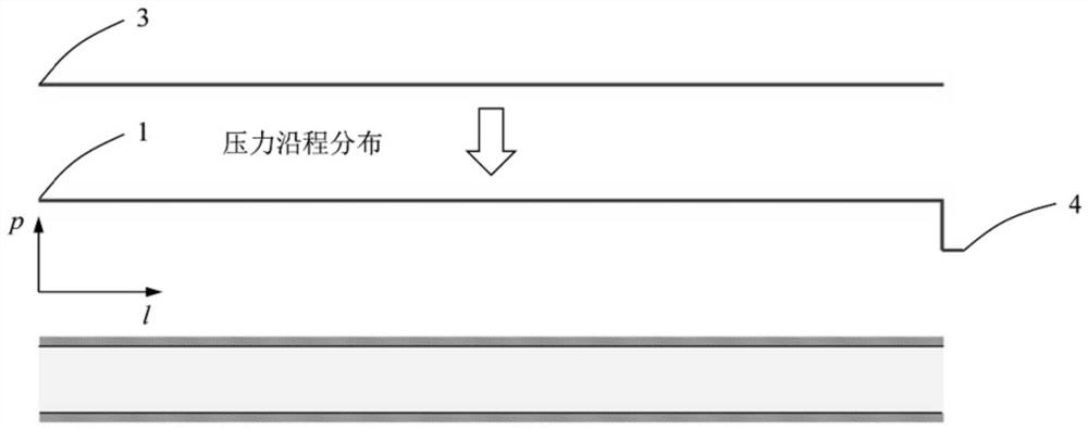
[0076] Based on the performance parameters of the inlet closed end and the performance parameters of the detonation wave front of the pulse detonation tube, the outlet performance parameters of the se...

Embodiment 2

[0152] refer to Figure 5 , an embodiment of the present invention provides a pulse detonation tube performance calculation device, including:

[0153] The exhaust stage is divided into stages, which is used to divide the exhaust stage of the pulse detonation tube into: the first stage in which the inlet of the pulse detonation tube is closed and the second stage in which the inlet of the pulse detonation tube is opened;

[0154] The first-stage pulse detonation tube outlet performance parameter acquisition module is used to obtain the performance parameters of the closed inlet end of the pulse detonation tube and the performance parameters after the detonation wave of the pulse detonation tube, according to the uniform zone length and expansion after the detonation wave Calculate the weighted average of the zone length to obtain the outlet performance parameters of the first-stage pulse detonation tube;

[0155] The second-stage pulse detonation tube outlet performance param...


PUM


Abstract

The invention provides a pulse detonation tube performance calculation method and device. The method comprises the steps that a detonation process in a full cycle period of a pulse detonation tube is divided into an exhaust stage and a scavenging stage, the exhaust stage is divided into a first stage in which an inlet of the pulse detonation tube is closed and a second stage in which the inlet of the pulse detonation tube is opened, and therefore parameters such as total enthalpy and total pressure of an outlet of the pulse detonation tube in each stage are analyzed; and finally, the performance of the pulse detonation tube is rapidly obtained through weighted averaging in different forms, the calculation precision is equivalent to that of one-dimensional unsteady simulation, the calculation process is simplified, the calculation workload is smaller than that of an existing method, the calculation precision is high, and unification of accuracy and convenience is realized.

Description

technical field [0001] The invention relates to performance calculation of a pulse detonation tube, in particular to a method and device for calculating the performance of a pulse detonation tube. Background technique [0002] The pulse detonation tube works periodically according to a certain frequency, and the thermodynamic parameters such as the total enthalpy and total pressure at the outlet change back and forth with time. In order to characterize the comprehensive performance of the pulse detonation tube, it is necessary to determine the total enthalpy and total pressure at the outlet according to the flow state at the inlet. The current calculation methods for the performance of pulse detonation tubes mainly include the steady-state limit method, the closed-end method and the characteristic diagram method. The steady-state limit method assumes that the knocking frequency is infinite, and based on the theoretical analysis results, the highest parameter after the knock...

Claims


Application Information

Patent Timeline
IPC IPC(8): F02K7/20F02K9/96
CPCF02K7/20F02K9/96Y02T90/00
Inventor 李凤超薛然然李瑞明贾真姚轩宇
Owner AERO ENGINE ACAD OF CHINA
Learn More