
Fault identification method for double-terminal protection of DC power grid

A technology for fault identification and DC power grid, which is applied in the fault location, fault detection according to the conductor type, and electrical measurement. It can solve the problem of limited ability to withstand transition resistance, double-terminal protection method is difficult to meet protection quickness, and converter station blocking To achieve the effect of improving the ability to withstand transition resistance, facilitating real-time and intuitive judgment, and meeting the requirements of quick movement

Active Publication Date: 2021-12-21
CHONGQING UNIV
View PDF0 Cites 0 Cited by
  • Summary
  • Abstract
  • Description
  • Claims
  • Application Information

AI Technical Summary

Problems solved by technology

Slow protection action will cause all converter stations to be blocked or even power outage in the whole network, so DC power grid protection must quickly identify and eliminate faults
The DC line protection schemes that have been proposed so far are not yet mature. The single-ended protection method generally has the defects of difficult threshold value setting, limited ability to withstand transition resistance, and the protection range is not the full length of the line. The double-ended protection method is difficult to meet the requirements of protection quickness. , affecting the operational reliability of the flexible HVDC system

Method used


Image

  • Fault identification method for double-terminal protection of DC power grid
  • Fault identification method for double-terminal protection of DC power grid
  • Fault identification method for double-terminal protection of DC power grid

Examples


Embodiment Construction

[0032] The present invention will be further described in detail below with reference to the accompanying drawings and preferred embodiments.

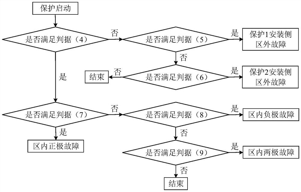
[0033] refer to figure 1 As shown, a fault identification method for double-terminal protection of a DC power grid includes the following steps:

[0034] The instantaneous current and instantaneous voltage on both sides of the line are collected in real time. When the current change rate on either side exceeds the protection start threshold g, it is judged that a fault has occurred, and the fault current and fault voltage are obtained. g is set according to the maximum load current change rate, and the threshold g is set to 0.5kA / ms. That is, when k exceeds the threshold g, the protection is activated.

[0035] Once the current change rate at the sampling time exceeds the protection start threshold, it can be judged that a fault has occurred, and the instantaneous current and instantaneous voltage corresponding to the sampling time c...


PUM


Abstract

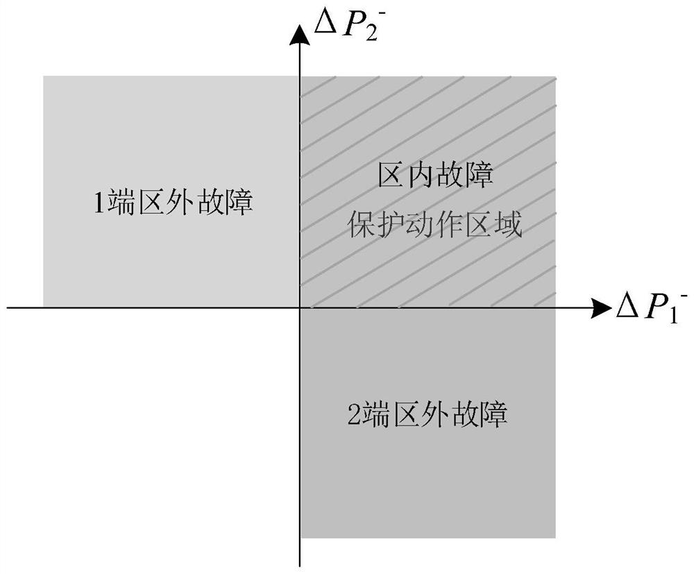
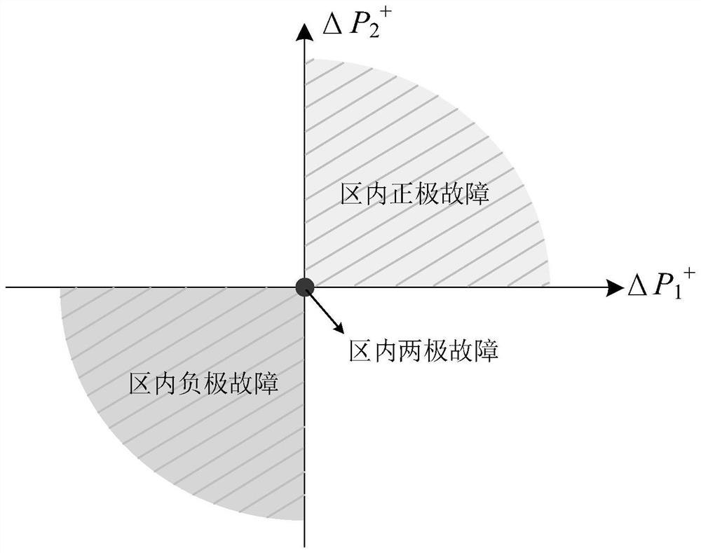
The invention relates to the technical field of DC power systems, and discloses a fault identification method for double-terminal protection of a DC power grid, which collects instantaneous current and instantaneous voltage on both sides of the line in real time, and when the current change rate on any side exceeds the protection start threshold , then it is judged that a fault has occurred, and the fault current and fault voltage are obtained; according to the fault current and fault voltage and the DC current and DC voltage before the fault, the instantaneous power difference of the positive and negative fault components on both sides of the line and the positive and negative fault components are calculated respectively. The instantaneous power sum of the components; judge the fault area according to the polarity of the instantaneous power difference of the positive and negative fault components on both sides of the line, and then judge the fault pole according to the instantaneous power sum of the positive and negative fault components. The invention solves the technical problem of how to improve the quickness and accuracy of fault identification. On the premise of meeting the requirement of protection selectivity, the protection range is close to the full length of the line, and has better ability to withstand transition resistance.

Description

technical field [0001] The invention relates to the technical field of direct current power systems, in particular to the technical field of fault identification for double-terminal protection of direct current power grids. Background technique [0002] With the development of power electronics technology, flexible DC transmission based on modular multi-level converters has developed rapidly. Compared with traditional HVDC transmission, flexible DC transmission has the advantages of high power quality, low loss, and flexible and independent control of active and reactive power. , large transmission capacity, no commutation failure and other technical characteristics. Among them, the multi-terminal flexible DC transmission system can realize multi-power supply and multi-drop power reception. Compared with the point-to-point DC transmission system, it can reduce line costs, improve power supply reliability, flexibility and system redundancy. It is the future power grid. inevi...

Claims


Application Information

Patent Timeline
Patent Type & Authority Patents(China)
IPC IPC(8): G01R31/08
CPCG01R31/086G01R31/088
Inventor 王洪彬周念成王强钢倪静怡廖建权魏能峤于大川
Owner CHONGQING UNIV
Learn More