Liftable table

A technology of lifting table and lifting mechanism, which is applied in the field of lifting table, can solve the problems of difficult tabletop speed, complex structure of table body, adjustment level, etc., and achieve the effect of improving user experience, simplifying table body structure, and enhancing stability

Pending Publication Date: 2021-06-22
NINGBO LEADER INTELLIGENT DEVICE TECH CO LTD
View PDF0 Cites 0 Cited by
  • Summary
  • Abstract
  • Description
  • Claims
  • Application Information

AI Technical Summary

Problems solved by technology

[0002] Lifting desks are office equipment widely promoted and applied in modern office spaces. The height adjustment of the desktop is mainly achieved by adjusting the height of the table legs to meet the needs of people of different heights. However, most of the existing lifting desks can only be used by users. Sitting and standing use, sitting and working for a long time to maintain an unreasonable posture and long-term stiffness is not conducive to health, and the damage to the lumbar muscles and spine is very serious. table
However, there are many defects in the desk tables currently on the market. For example, most of the legs are set as the structure of the telescopic sleeve, and the length of the legs is adjusted through nuts and screws. Quickly adjust the level; In addition, most of the common table tables that can be lifted vertically are equipped with X-shaped lifting brackets at both ends of the table body, and the push rods are lifted and lowered between the crossed rod bodies. The table designed in this way When heavy objects are placed on one side of the table body for a long time, it is difficult to maintain the level due to uneven force on both ends of the table, and it is necessary to ensure the same lifting speed of the lifting push rods on both sides, which makes the structure of the entire table body complex and expensive

Method used


Image

  • Liftable table
  • Liftable table
  • Liftable table

Examples


Embodiment Construction

[0022] The present invention will be further described in detail below in conjunction with the accompanying drawings and embodiments.

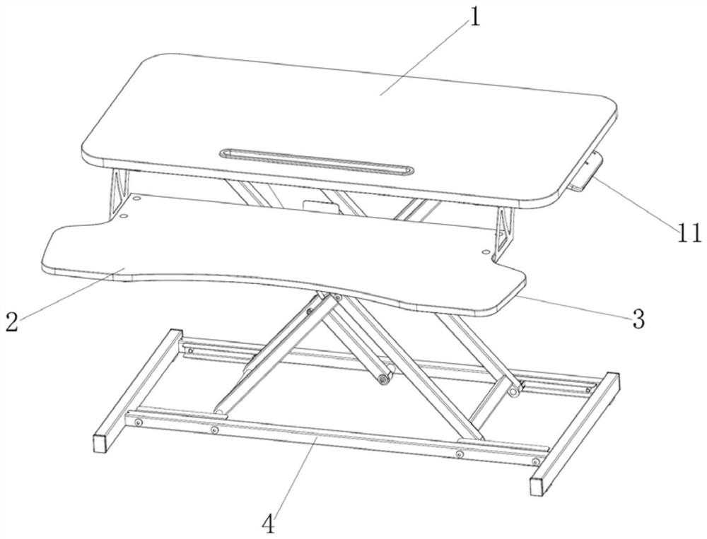
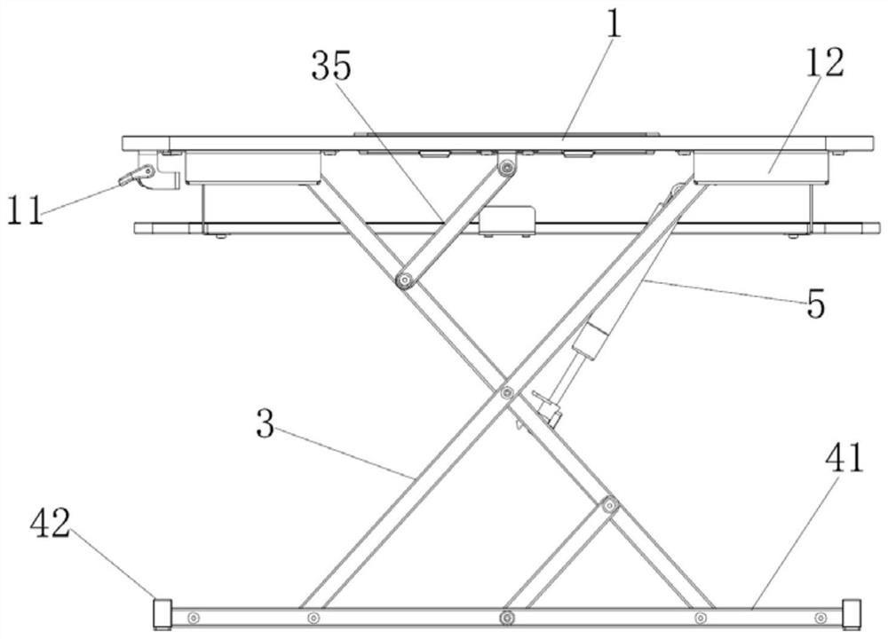
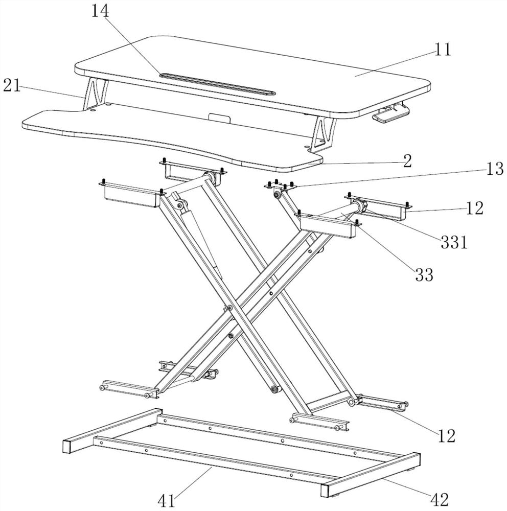
[0023] like Figure 1 to Figure 4 As shown, the liftable table top table of this embodiment includes an upper panel 1 , a lower panel 2 , a bracket assembly 3 arranged on the lower side of the upper panel 1 , and a base 4 arranged at the bottom of the bracket assembly 3 . The upper panel 1 generally places computer screens, laptops, etc., and the lower panel 2 places keyboards, mice, etc., and the side of the upper panel 1 close to the lower panel 2 is provided with a waist-shaped hole-shaped card slot 14, and a card slot is installed in the card slot 14. The card slot cover is fixed in the card slot 14 through two sets of buckles symmetrically arranged on the outer wall, and three through holes are evenly arranged at the bottom of the card slot cover, which can be used to place mobile phones, tablet computers, etc. In this embodiment, the he...


PUM


Abstract

A liftable table comprises an upper panel, a lower panel, a support assembly and a base, a plurality of sliding rails are symmetrically arranged on the lower side of the upper panel, the base comprises a first bottom rod and a second bottom rod which are arranged in parallel, a plurality of sliding rails are symmetrically arranged on the inner side of the first bottom rod, and the support assembly comprises two pairs of X-shaped first supports and second supports. Transmission shafts with sliding blocks at the two ends are arranged between the top ends of the first supports and the top ends of the second supports, the sliding blocks are arranged at the bottom ends of the first supports and the second supports through rotating shafts, the support assembly is movably connected between the upper panel and the base through cooperation of the sliding blocks and the sliding rails, and a lifting mechanism is arranged between the second supports and the transmission shafts below the upper panel. Compared with the prior art, the table has the advantages that the lifting mechanism is arranged to be matched with the handle of the upper panel, so that the height of the table can be quickly and stably adjusted; by arranging the X-shaped support assembly, reinforcing arms and supporting rods, the stability of the support assembly is enhanced, the height of the support assembly is integrally adjusted in a coordinated mode, and the structure of the table is simplified.

Description

technical field [0001] The invention relates to the technical field of lift tables, in particular to an upper table with a liftable table. Background technique [0002] Lifting desks are office equipment widely promoted and applied in modern office spaces. The height adjustment of the desktop is mainly achieved by adjusting the height of the table legs to meet the needs of people of different heights. However, most of the existing lifting desks can only be used by users. Sitting and standing use, sitting and working for a long time to maintain an unreasonable posture and long-term stiffness is not conducive to health, and the damage to the lumbar muscles and spine is very serious. table. However, there are many defects in the desk tables currently on the market. For example, most of the legs are set as the structure of the telescopic sleeve, and the length of the legs is adjusted through nuts and screws. Quickly adjust the level; In addition, most of the common table table...

Claims


Application Information

Patent Timeline
Patent Type & Authority Applications(China)
IPC IPC(8): A47B9/16A47B21/02A47B13/08A47B13/02
CPCA47B9/16A47B21/02A47B13/08A47B13/02A47B2009/006A47B21/04A47B2200/0085A47B9/18A47B21/0314
Inventor 王毅勇梅滔吕俊杰任斌蒋守诚茹军辉沈晨励凯锋任智俊
Owner NINGBO LEADER INTELLIGENT DEVICE TECH CO LTD
Why Eureka
Try Eureka