
High-lift wind turbine airfoil

A technology of airfoil shape and lift, applied to wind engines, wind engines consistent with the wind direction, engines, etc., can solve problems such as easy airflow separation, lower economic benefits of wind turbine rotors, and increase drag coefficient

Pending Publication Date: 2021-06-08
LANZHOU UNIVERSITY OF TECHNOLOGY
View PDF0 Cites 0 Cited by
  • Summary
  • Abstract
  • Description
  • Claims
  • Application Information

AI Technical Summary

Problems solved by technology

However, although this type of airfoil can guarantee a low drag coefficient at a small angle of attack, it is prone to airflow separation at a large angle of attack, thereby reducing the lift coefficient, increasing the drag coefficient, and reducing the wind turbine rotor. Economical, so vertical axis wind turbines are not aerodynamically efficient at low wind speeds

Method used


Image

  • High-lift wind turbine airfoil
  • High-lift wind turbine airfoil
  • High-lift wind turbine airfoil

Examples


Embodiment Construction

[0032] In order to make the purpose, technical solution and advantages of the present invention more clear, the present invention will be further described in detail below in conjunction with the accompanying drawings and examples, wherein the examples are theoretical calculation and analysis of the present invention. It should be understood that the specific embodiments described here are only used to explain the present invention, not to limit the present invention.

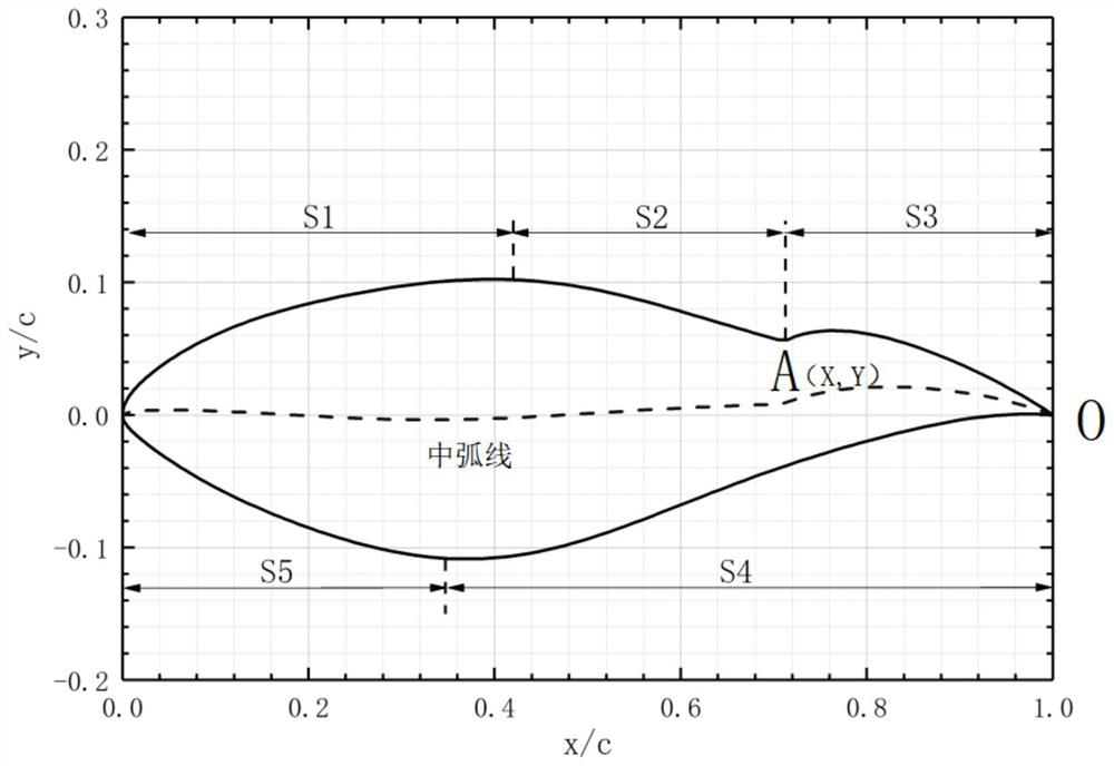
[0033] The invention discloses a high-lift wind turbine airfoil, which combines Figure 1 ~ Figure 3 As shown, the structure of the high-lift wind-powered airfoil is based on the curved profile of the S809 airfoil, and the structure of the high-lift wind-powered airfoil is described as:

[0034] The S809 airfoil profile and the NACA4412 airfoil profile are frontally projected in the same X-Y coordinate system to obtain the S809 airfoil profile and the NACA4412 airfoil profile respectively, and the trailing edge...


PUM


Abstract

The invention discloses a high-lift wind turbine airfoil. The airfoil is formed by the following steps of: taking an S809 airfoil as a basic profile, multiplying the chord length of an NACA4412 airfoil by a scale factor alpha, shrinking the NACA4412 airfoil, and rotating the shrunk airfoil at a fixed angle beta based on a trailing edge point; and at the trailing edge, when the vertical coordinate of the upper surface of the S809 airfoil is smaller than the vertical coordinate of the NACA4412 airfoil, replacing the upper surface of the part of the S809 airfoil with the surface of the NACA4412 airfoil. According to the high-lift wind turbine airfoil, the middle section position of the upper surface of the airfoil is in smooth transition, and a small adverse pressure gradient of the airfoil under a large angle of attack is guaranteed to inhibit airflow separation, the airfoil has a larger lift coefficient, a larger stalling angle and smaller resistance, and the wind energy absorption efficiency of a wind wheel of a wind generating set is improved.

Description

technical field [0001] The invention belongs to the technical field of wind power generation, and in particular relates to a high-lift wind power airfoil used for a wind power generating set. Background technique [0002] For the geometric shape of a wind blade, the airfoil is the "gene" of the blade, and its aerodynamic performance directly affects the aerodynamic performance of the wind turbine blade. Therefore, the design of the aerodynamic shape of the wind turbine rotor blade is inseparable from the airfoil design. Before the 1980s, the airfoils of wind turbines often used aviation airfoils. However, aviation airfoils are usually designed under pressure-sonic conditions, and the aerodynamic performance cannot be effectively guaranteed under low-speed conditions. In addition, there are disadvantages that the thickness is small and cannot meet the structural requirements. At the same time, the stall of the airfoil at high angles of attack serious. Therefore, the current...

Claims


Application Information

Patent Timeline
Patent Type & Authority Applications(China)
IPC IPC(8): F03D1/06
CPCF03D1/0633Y02E10/72
Inventor 王清余牧遥李寿图李德顺
Owner LANZHOU UNIVERSITY OF TECHNOLOGY
Learn More