
Pit digging device for agricultural planting

A technology for digging and agriculture, which is applied in the field of digging devices, and can solve the problems of time-consuming and labor-intensive manual digging, affecting planting time, time-consuming and labor-intensive problems, etc.

Inactive Publication Date: 2021-05-04
JIANGXI WANGNONG AGRI MACHINERY MFG
View PDF0 Cites 0 Cited by
  • Summary
  • Abstract
  • Description
  • Claims
  • Application Information

AI Technical Summary

Problems solved by technology

[0004] In order to overcome the fact that manual digging is more time-consuming and labor-intensive, which reduces people's work efficiency, due to the large area of ​​the land, it may be necessary to dig a large number of pits. If large-scale production and planting will affect the planting time, time-consuming and labor-intensive problems may also occur. Disadvantages, technical problems: provide a digging device for agricultural planting that is easy to move, automatically digs pits and automatically spreads materials

Method used


Image

  • Pit digging device for agricultural planting
  • Pit digging device for agricultural planting
  • Pit digging device for agricultural planting

Examples


Embodiment 1

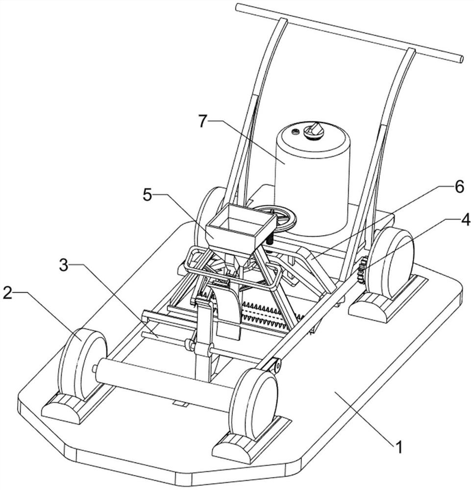
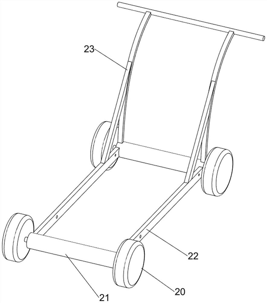
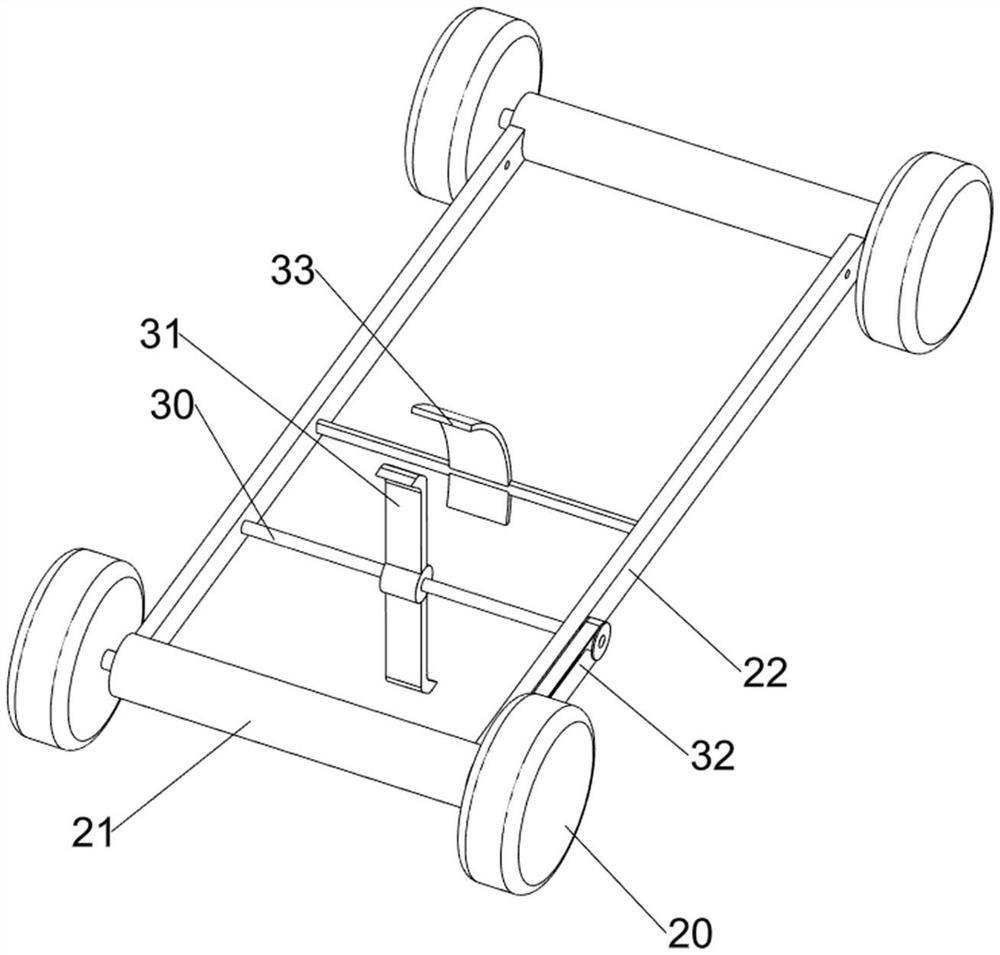
[0033] A planing device for agricultural planting, such as figure 1 , figure 2 and image 3 As shown, it includes a base 1, a moving mechanism 2 and a digging mechanism 3, the base 1 is placed with a moving mechanism 2, and the moving mechanism 2 is provided with a digging mechanism 3.

[0034] The moving mechanism 2 includes a roller 20, a first mounting block 21, a first connecting block 22 and a second connecting block 23, there are two first mounting blocks 21, and a first connecting block 22 is arranged symmetrically between the first mounting blocks 21 , the left and right sides of the first mounting block 21 are rotatably provided with rollers 20, the rollers 20 cooperate with the base 1, and the top of the first mounting block 21 on the rear side is provided with a second connecting block 23.

[0035] Planing hole mechanism 3 comprises rotating shaft 30, rotating block 31, transmission assembly 32 and baffle plate 33, and rotating type is provided with rotating shaf...

Embodiment 2

[0038] On the basis of Example 1, such as Figure 4 , Figure 5 , Figure 6 , Figure 7 , Figure 8 , Figure 9 , Figure 10 , Figure 11 and Figure 12 As shown, a booster mechanism 4 is also included, and the booster mechanism 4 includes a second mounting block 40, a biaxial motor 41, a first gear 42 and a second gear 43, and a second mounting block is provided between the rear sides of the first connecting block 22. Block 40, the middle part of the second mounting block 40 is provided with a biaxial motor 41, the left and right sides of the output shaft of the biaxial motor 41 are provided with a first gear 42, and the inner side of the rear side roller 20 is provided with a second gear 43, and the same side is equipped with a second gear 43. The first gear 42 and the second gear 43 mesh with each other.

[0039] People start the biaxial motor 41, the output shaft of the biaxial motor 41 will drive the first gear 42 to rotate, the first gear 42 will drive the second...


PUM


Abstract

The invention relates to a pit digging device, in particular to a pit digging device for agricultural planting. The technical problem to be solved is to provide the pit digging device for the agricultural planting, which is convenient to move, can automatically dig pits and can automatically scatter materials. According to the technical scheme, the pit digging device for the agricultural planting comprises a base, a moving mechanism placed on the base and a pit digging mechanism arranged on the moving mechanism. The pit digging device has the beneficial effects that under the action of the pit digging mechanism, people push a second connecting block forwards, the second connecting block can drive a first mounting block and a first connecting block to move forwards, meanwhile, the first mounting block can drive rollers to rotate, the rollers on the front side can drive a transmission assembly and a rotating shaft to rotate, the rotating shaft can drive a rotating block to rotate, and when the rotating block is in contact with the ground, the land is dug.

Description

technical field [0001] The invention relates to a digging device, in particular to a digging device for agricultural planting. Background technique [0002] In the process of farmland production and planting, digging holes is a labor-intensive task. At present, people plan holes on the ground before planting. Generally, the work of digging holes is completed by pressing tools. This operation may make part of the soil The size of the pits is different, and manual digging is more time-consuming and laborious, which reduces people's work efficiency. Due to the large area of ​​the land, it may be necessary to dig a large number of pits. If large-scale production and planting will affect the planting time, it may also occur A time-consuming situation. [0003] Therefore, it is particularly necessary to design a digging device for agricultural planting that is easy to move, automatically digs and spreads materials automatically, which can save some troubles that most manual opera...

Claims


Application Information

Patent Timeline
IPC IPC(8): A01C5/04
CPCA01C5/04
Inventor 曾志伟
Owner JIANGXI WANGNONG AGRI MACHINERY MFG
Learn More