
Control circuit, switching power supply and electronic equipment

A technology of control circuits and switching circuits, which is applied in the direction of high-efficiency power electronic conversion, control/regulation systems, electrical components, etc., and can solve problems affecting energy efficiency certification and high power consumption

Active Publication Date: 2021-04-23
GUANGDONG OPPO MOBILE TELECOMM CORP LTD
View PDF7 Cites 0 Cited by
  • Summary
  • Abstract
  • Description
  • Claims
  • Application Information

AI Technical Summary

Problems solved by technology

[0003] In the related art, the output voltage of the PFC circuit is a constant voltage, that is, the output voltage of the PFC circuit maintains a normal 400V output voltage regardless of the state of the electronic device with the built-in PFC circuit. Therefore, the output voltage of the PFC circuit is Resistors will generate losses, and their power consumption is high, which may even affect energy efficiency certification

Method used


Image

  • Control circuit, switching power supply and electronic equipment
  • Control circuit, switching power supply and electronic equipment
  • Control circuit, switching power supply and electronic equipment

Examples


Embodiment Construction

[0035] In order to make the purpose, technical solution and advantages of the present application clearer, the present application will be further described in detail below in conjunction with the accompanying drawings and embodiments. It should be understood that the specific embodiments described here are only used to explain the present application, and are not intended to limit the present application.

[0036] It can be understood that the terms "first", "second", etc. used in this application may be used to describe various elements herein, but these elements are not limited by these terms. These terms are only used to distinguish one element from another element. For example, a first weld could be termed a second weld, and, similarly, a second weld could be termed a first weld, without departing from the scope of the present application. Both the first solder joint and the second solder joint are solder joints, but they are not the same solder joint.

[0037] In addit...


PUM


Abstract

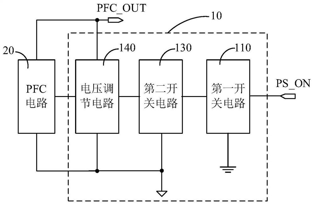
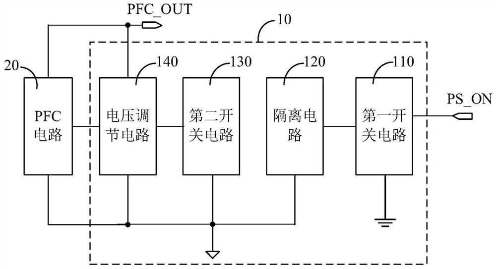
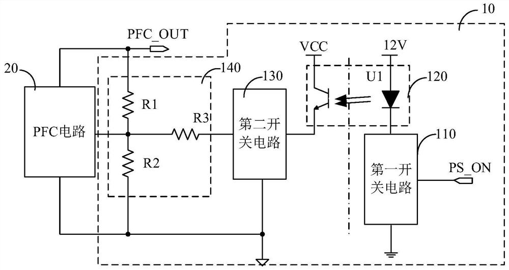
The invention relates to a control circuit, a switching power supply and electronic equipment, and the control circuit comprises a first switching circuit having a control terminal used for receiving a control signal of a control system, a second switching circuit having a control terminal connected with a second end of the first switching circuit and a first end connected with a ground terminal of a PFC circuit, and a voltage regulating circuit connected with the PFC circuit, the second end of the second switching circuit and the ground terminal of the PFC circuit; and the resistance value of the voltage regulating circuit is in positive correlation with the output voltage; the first switching circuit and the second switching circuit are used for selectively conducting the control signal to the control path of the voltage regulating circuit under the control of the control signal so as to regulate the resistance value of the voltage regulating circuit, so that the regulation of the output voltage of the output end of the PFC circuit can be realized, and the standby power consumption can be further reduced.

Description

technical field [0001] The present application relates to the technical field of wearable devices, in particular to a control circuit, a switching power supply and electronic equipment. Background technique [0002] A power factor correction (Power Factor Correction, PFC) circuit can boost an input voltage to an output voltage, and the output voltage is higher than the input voltage, and the output voltage is generally set to 400V. [0003] In the related art, the output voltage of the PFC circuit is a constant voltage, that is, the output voltage of the PFC circuit maintains a normal 400V output voltage regardless of the state of the electronic device with the built-in PFC circuit. Therefore, the output voltage of the PFC circuit is Resistors will generate losses, and their power consumption is high, which may even affect energy efficiency certification. Contents of the invention [0004] The embodiment of the present application provides a control circuit, a switching p...

Claims


Application Information

Patent Timeline
Patent Type & Authority Applications(China)
IPC IPC(8): H02M1/42H02M3/158
CPCH02M1/42H02M3/158Y02B70/10
Inventor 黄晓东
Owner GUANGDONG OPPO MOBILE TELECOMM CORP LTD
Learn More