
Method and device for distance measurement

A technology for measuring pulses and measuring areas, which is applied in the field of optical distance measurement, and can solve the problems of reducing method and equipment performance, low resolution, etc.

Pending Publication Date: 2021-03-23
MICROVISION
View PDF0 Cites 2 Cited by
  • Summary
  • Abstract
  • Description
  • Claims
  • Application Information

AI Technical Summary

Problems solved by technology

Therefore, large measurement areas can only be measured with low resolution due to the predetermined number of receiving elements
In addition, the range and signal-to-noise ratio (SNR) are also small due to the variability of the individual receiving elements, thereby degrading the performance of the method and apparatus

Method used


Image

  • Method and device for distance measurement
  • Method and device for distance measurement
  • Method and device for distance measurement

Examples


Embodiment Construction

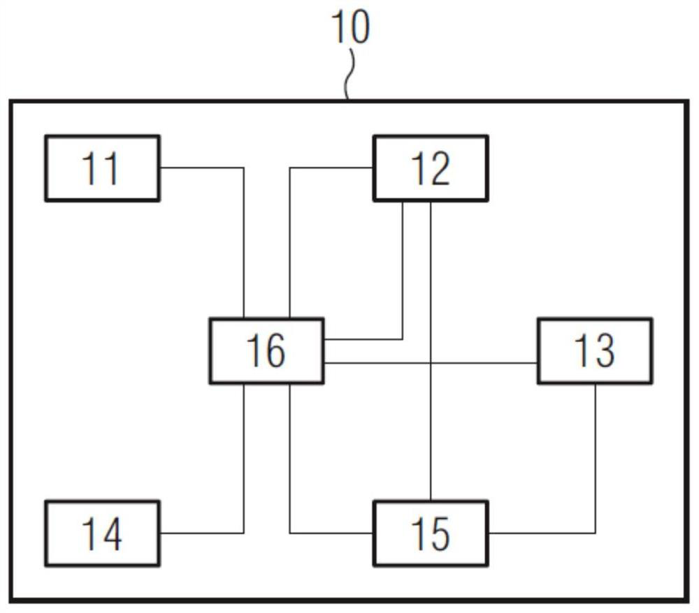
[0054] figure 1 A flow chart of a method 100 for distance measurement according to the invention is shown.

[0055] The method 100 comprises creating 101 at least one frame, wherein 3D information of at least one sub-area of ​​the measurement area is determined as part of the frame. A time budget for frames is divided 102 between a first stage for determining at least one region of interest and a second stage for determining 3D information from the at least one region of interest.

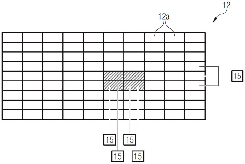
[0056] Method 100 includes performing 103 a first phase, wherein, in the first phase, a plurality of measurement pulses are transmitted 107 by means of transmission unit 11 and reflected measurement pulses are received 108 by means of reception unit 12 . Based on the reflected measurement pulses, 2D information of the measurement area is determined 109 . In particular, a two-dimensional (2D) intensity image is further created 110 .

[0057] The lighting for the first stage may further be determi...


PUM


Abstract

Disclosed are a method and device for distance measurement. A method for optical distance measurement, comprising a creation of at least one frame, including determining 3D information of at least onesubregion of a measuring region. A time budget for creating the frame is split between a first phase for assessing at least one region of interest, and a second phase for determining 3D information from the at least one region of interest. During the first phase a plurality of measuring pulses is emitted by a transmitting unit, and reflected measuring pulses are received by a receiving unit, wherein 2D information of the measuring region is determined, wherein at least one region of interest is assessed from the 2D information. During the second phase a plurality of measuring pulses is emitted by a transmitting unit, and reflected measuring pulses are received by the receiving unit, wherein 3D information of the at least one region of interest is determined as part of the second phase.

Description

technical field [0001] The invention relates to a method and a device for optical distance measurement. Background technique [0002] Optical distance measurement, in particular for driverless navigation of vehicles, is known from the prior art. Optical distance measurement is based on the time-of-flight principle, in which a measuring pulse is emitted periodically, which is reflected on an object, and the reflected measuring pulse is detected. By determining the flight time of the measurement pulse from the sensor to the object and back to the sensor, conclusions can be drawn about the distance to these objects with the aid of the speed of light. [0003] Corresponding devices for optically measuring distances are typically formed as LIDAR (short for "Light Detection and Ranging") sensors, which consist of a transmitting and receiving unit which effectively senses the measured area, eliminating the need for mechanical parts. Thus, on the emission side, electronic scannin...

Claims


Application Information

Patent Timeline
Patent Type & Authority Applications(China)
IPC IPC(8): G01S17/10G01S17/26G01S17/89G01S17/894G01S7/4863G01S7/4861G01S7/481G01S7/48
CPCG01S17/10G01S17/26G01S17/894G01S17/89G01S7/481G01S7/4861G01S7/4863G01S7/4802G01S17/931G01S7/48G01S17/86G01S13/89G01S17/02G01S7/4808G01S7/484G01S7/4865G01S7/487
Inventor 云萨尔·卡布克
Owner MICROVISION
Learn More