A Gait Phase Recognition Method Based on Inertial Sensor

An inertial sensor and recognition method technology, applied in the field of gait phase recognition, can solve the problems of adaptive dependence, prone to misjudgment and missed judgment, poor robustness, etc., to improve robustness and ease of use, and facilitate rapid The effect of putting on and taking off and improving the robustness

Active Publication Date: 2022-04-22
BEIJING RES INST OF PRECISE MECHATRONICS CONTROLS
View PDF6 Cites 0 Cited by
  • Summary
  • Abstract
  • Description
  • Claims
  • Application Information

AI Technical Summary

Problems solved by technology

[0005] (1) Gait phase recognition technologies based on pressure insoles, light-capturing camera equipment, electromechanical or EEG acquisition equipment have high requirements for hardware. These equipment are not convenient for users to wear quickly and some of them are relatively expensive
[0006] (2) Problems with machine learning gait phase recognition algorithms based on inertial sensors: machine learning algorithms require a large amount of training data to improve performance, so it takes a certain amount of time to collect training sets for the algorithm, which cannot be done for users with large differences Ready to wear and use; the generalization ability of machine learning algorithms varies, and the adaptability to different terrains depends on the quality of the training set; it is difficult to control the delay of machine learning algorithms at the millisecond level, and there is a sense of lag in actual use
[0007] (3) Problems with the threshold discrimination gait phase recognition algorithm based on inertial sensors: the threshold of the threshold discrimination algorithm is difficult to define, and a large amount of data is required to provide a basis; the threshold discrimination algorithm continuously adjusts parameters according to different users and terrain needs, and is robust Poor performance; Threshold discrimination algorithms are prone to misjudgments and missed judgments for special actions in the gait cycle

Method used


Image

  • A Gait Phase Recognition Method Based on Inertial Sensor
  • A Gait Phase Recognition Method Based on Inertial Sensor
  • A Gait Phase Recognition Method Based on Inertial Sensor

Examples


Embodiment Construction

[0047] The present invention will be further described in detail below in conjunction with the accompanying drawings and specific embodiments.

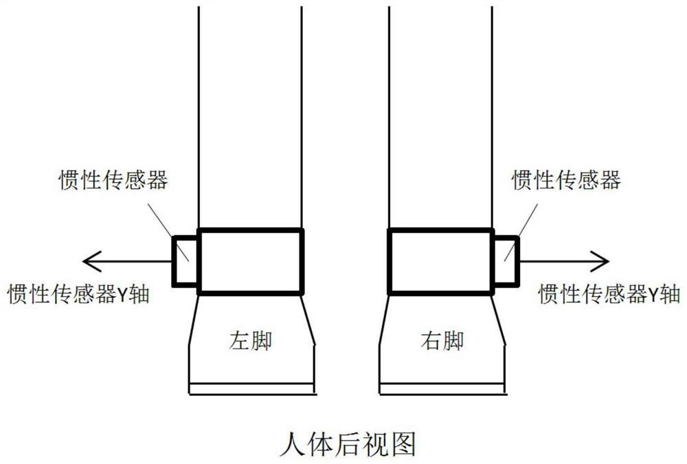
[0048] The invention discloses a gait phase identification method based on an inertial sensor, which utilizes the body side angular velocity collected by the inertial sensor bound at the ankle to perform extreme value discrimination. A complete gait cycle can be roughly divided into two phases, the swing state and the support state, and the support state can be divided into four stages in sequence: heel strike, full foot strike, heel off the ground, and forefoot off the ground. When in the stage of full-foot landing in the support state, the foot is relatively static relative to the ground, that is, the lateral angular velocity at the ankle is close to zero. Using the characteristic of angular velocity "touching the ground is zero", comparing the calibration results of pressure insoles, it can be seen that the entire supporting state ...


PUM


Abstract

The invention discloses a gait phase identification method based on an inertial sensor, which utilizes the body side angular velocity collected by the inertial sensor bound at the ankle to perform extreme value discrimination. A complete gait cycle can be roughly divided into two phases, the swing state and the support state, and the support state can be divided into four stages in sequence: heel strike, full foot strike, heel off the ground, and forefoot off the ground. When in the stage of full-foot landing in the support state, the foot is relatively static relative to the ground, that is, the lateral angular velocity at the ankle is close to zero. Using the characteristic of angular velocity "touching the ground is zero", comparing the calibration results of pressure insoles, it can be seen that the entire supporting state phase can be identified by detecting the two maximum values ​​of the input angular velocity, which can achieve high accuracy, low delay, and low hardware requirements. and easy-to-use targets.

Description

technical field [0001] The invention relates to a gait phase recognition method based on an inertial sensor, and belongs to the technical field of gait phase recognition. Background technique [0002] The exoskeleton robot is a human-machine system, and various information needs to be exchanged between the human body movement and the exoskeleton movement. The exoskeleton needs to recognize the gait of the human body and the movement intention of the human body to drive the movement of the exoskeleton. Gait information needs to be analyzed through the gait data collected by the sensor system. The gait data collected by different sensor systems are also different, so the gait characteristics are also different, so the methods of gait recognition are also different. The main gait data include: joint angle data, acceleration data of the limbs, myoelectric signals of relevant muscle groups, brain wave signals, plantar pressure signals, and video-based image data, etc. [0003]...

Claims


Application Information

Patent Timeline
Patent Type & Authority Patents(China)
IPC IPC(8): B25J9/00B25J9/16
CPCB25J9/0006B25J9/16B25J9/1694
Inventor 张礼策尹业成闫国栋刘家伦刘志军
Owner BEIJING RES INST OF PRECISE MECHATRONICS CONTROLS
Why Eureka
Try Eureka