Rapid flattening device for feed production and screening and flattening method
A feed and fast technology, applied in chemical instruments and methods, filtration, solid separation, etc., can solve the problems of low screening speed, too many feed raw materials, and the production efficiency of feed production line cannot be further improved, so as to achieve the goal of improving production efficiency Effect
- Summary
- Abstract
- Description
- Claims
- Application Information
AI Technical Summary
Problems solved by technology
Method used
Image
Examples
Embodiment 1
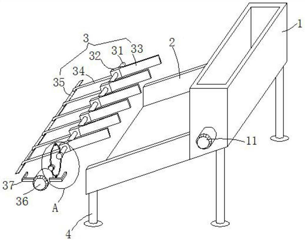
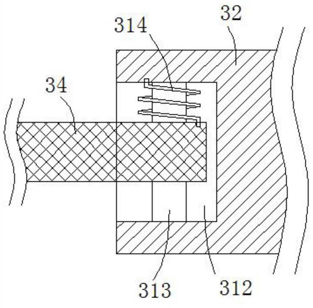
[0026] see Figure 1-4 , the present embodiment provides a fast flattening device and flattening method for feed production and screening, including a material guide plate 2, a feed hopper 1 and a flattening mechanism 3, and the front and rear ends of the material guide plate 2 are bent upward by 90 ° Form a baffle, which can prevent the feed from falling from the front and rear sides of the material guide plate 2, and the bottom surface of the feed hopper 1 The material guide plate 2 is all inclined to the left and lower by 45 degrees, so that it is convenient for the feed to slide down and carry out the screening operation. The bottom end of the left end face of the hopper 1 is fixedly welded on the right end face of the material guide plate 2, and the bottom end of the left end face of the feed hopper 1 is provided with a discharge port 14 that is flush with the bottom end face of the inner cavity of the feed hopper 1. The feed to be screened is filled into the inner cavity...
Embodiment 2
[0033] see Figure 1-4 , further improvements have been made on the basis of Example 1:
[0034] The front and rear ends on the left side of the bottom end surface of the material guide plate 2 and the front and rear ends on the right side of the bottom end surface of the feed hopper 1 are vertically provided with support legs 4, and four support legs 4 are used to support the material guide plate 2 and the feed hopper 1 .
[0035] The middle positions of the two C-shaped stainless steel elastic rods 39 are all rotatably sleeved with rotatable rolling balls 310. By setting the rotatable rolling balls 310, the C-shaped stainless steel elastic rods 39 pass through the inner surfaces of the rolling balls 310 and the material guide plate 2. The bottom end surface of the cavity is rolled and fitted to reduce the rolling friction force of the C-shaped stainless steel elastic rod 39 directly contacting the bottom end surface of the inner cavity of the material guide plate 2 .
PUM
 Abstract
Description
Claims
Application Information
 - R&D
- Intellectual Property
- Life Sciences
- Materials
- Tech Scout
- Unparalleled Data Quality
- Higher Quality Content
- 60% Fewer Hallucinations
Browse by: Latest US Patents, China's latest patents, Technical Efficacy Thesaurus, Application Domain, Technology Topic, Popular Technical Reports.
© 2025 PatSnap. All rights reserved.Legal|Privacy policy|Modern Slavery Act Transparency Statement|Sitemap|About US| Contact US: help@patsnap.com


