Photovoltaic junction box transplanter
A technology of volt junction box and transplanting machine, which is applied in the direction of coating, liquid coating device on the surface, etc., can solve the problems of low efficiency and high labor cost, reduce production cost, reduce labor consumption and use, reduce The effect of waste generation
- Summary
- Abstract
- Description
- Claims
- Application Information
AI Technical Summary
Problems solved by technology
Method used
Image
Examples
Embodiment 1
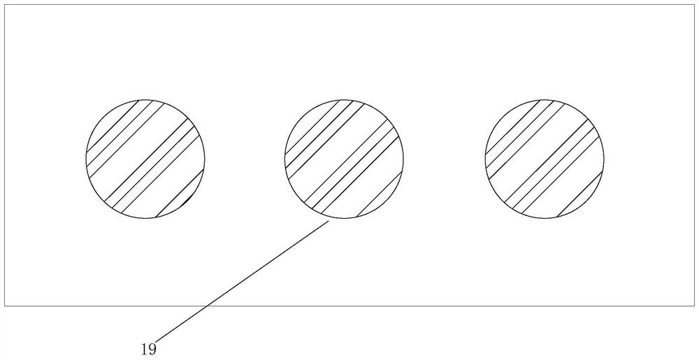
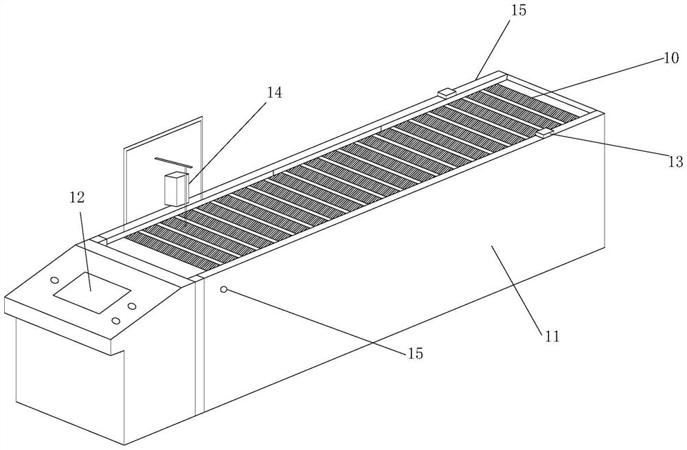
[0024] Such as Figures 1 to 4 As shown, the photovoltaic junction box transplanter of this embodiment includes a jig for fixing the photovoltaic junction box 20, and the photovoltaic junction box in the jig is placed by the operator after being filled with glue by the automatic gluing system 14 and transported. Platform 10, the fixture includes a fixture bottom plate 1, a photovoltaic junction box fixing groove 2 is provided on the top of the fixture bottom plate 1, and a magnet 19 for being adsorbed on the transmission platform is provided at the bottom of the fixture bottom plate 1; the transmission platform includes a housing 11 And the conveyor belt 16 embedded in the top of the housing 11 driven by the motor and a plurality of chain plates 17 for fixing the fixture on the conveyor belt 16, the two sides of the housing 11 are located at different ends with transmission platform start-stop switches 15, An automatic gluing system 14 is provided at the starting end on any si...
Embodiment 2
[0030] Such as Figures 1 to 4 As shown, the photovoltaic junction box transplanter of this embodiment includes a jig for fixing the photovoltaic junction box 20, and the photovoltaic junction box in the jig is placed by the operator after being filled with glue by the automatic gluing system 14 and transported. Platform 10, the fixture includes a fixture bottom plate 1, a photovoltaic junction box fixing groove 2 is provided on the top of the fixture bottom plate 1, and a magnet 19 for being adsorbed on the transmission platform is provided at the bottom of the fixture bottom plate 1; the transmission platform includes a housing 11 And the conveyor belt 16 embedded in the top of the housing 11 driven by the motor and a plurality of chain plates 17 for fixing the fixture on the conveyor belt 16, the two sides of the housing 11 are located at different ends with transmission platform start-stop switches 15, An automatic gluing system 14 is provided at the starting end on any si...
Embodiment 3
[0038] Such as Figures 1 to 4 As shown, the photovoltaic junction box transplanter of this embodiment includes a jig for fixing the photovoltaic junction box 20, and the photovoltaic junction box in the jig is placed by the operator after being filled with glue by the automatic gluing system 14 and transported. Platform 10, the fixture includes a fixture bottom plate 1, a photovoltaic junction box fixing groove 2 is provided on the top of the fixture bottom plate 1, and a magnet 19 for being adsorbed on the transmission platform is provided at the bottom of the fixture bottom plate 1; the transmission platform includes a housing 11 And the conveyor belt 16 embedded in the top of the housing 11 driven by the motor and a plurality of chain plates 17 for fixing the fixture on the conveyor belt 16, the two sides of the housing 11 are located at different ends with transmission platform start-stop switches 15, An automatic gluing system 14 is provided at the starting end on any si...
PUM
 Abstract
Description
Claims
Application Information
 - R&D
- Intellectual Property
- Life Sciences
- Materials
- Tech Scout
- Unparalleled Data Quality
- Higher Quality Content
- 60% Fewer Hallucinations
Browse by: Latest US Patents, China's latest patents, Technical Efficacy Thesaurus, Application Domain, Technology Topic, Popular Technical Reports.
© 2025 PatSnap. All rights reserved.Legal|Privacy policy|Modern Slavery Act Transparency Statement|Sitemap|About US| Contact US: help@patsnap.com


