A handling robot

A handling robot and robot technology, applied in the field of handling robots, can solve the problems of wafer breakage, wafer wear, and high friction, and achieve the effects of preventing breakage, reducing gap height, and reducing friction.

Active Publication Date: 2021-08-24
深圳市大族贝金装备有限公司
View PDF7 Cites 0 Cited by
  • Summary
  • Abstract
  • Description
  • Claims
  • Application Information

AI Technical Summary

Problems solved by technology

[0002] The polysilicon crystal is melted and pulled out of the monocrystalline silicon ingot, and then cut into thin wafers. During the production process of the wafer, it is necessary to use a handling robot to transport the wafer to the inspection machine for inspection, but the handling During the process of handling the wafer by the robot, the wafer is clamped by the gripper hand on the handling robot, and the wafer is fixed on the gripper hand before handling and transferring. Since the thickness of the wafer is very thin and it is brittle and hard characteristics, during the process of clamping the wafer, the gripper hand produces a large friction force with the surface of the wafer, which is easy to cause wear on the surface of the wafer. There is a certain gap height between the bottom surface of the circle and the inspection machine. When the wafer falls, it will have a falling force with the inspection machine, which will easily cause thinner wafers to break.

Method used


Image

  • A handling robot
  • A handling robot
  • A handling robot

Examples


Embodiment 1

[0024] as attached figure 1 to attach Figure 6 Shown:

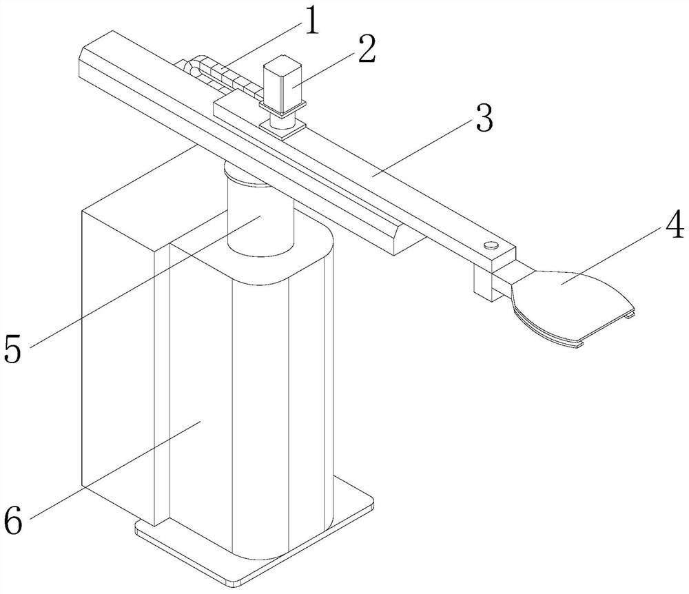
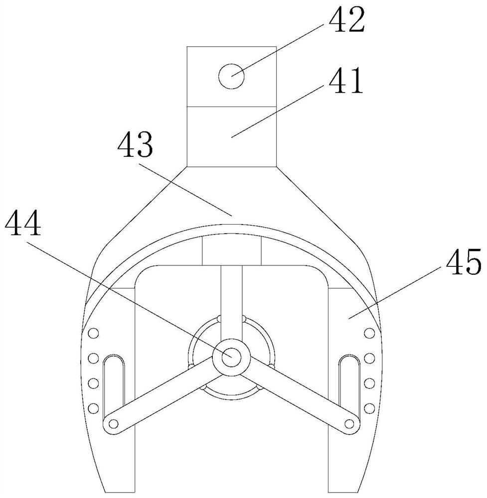
[0025] A kind of handling robot of the present invention, its structure comprises transmission belt 1, motor 2, support arm 3, clip hand 4, rotating shaft 5, robot host 6, described transmission belt 1 rotates synchronously with the output end of motor 2, and described motor 2 is installed on the top of the support arm 3, and the front end of the support arm 3 is provided with a clamping hand 4, the bottom of the support arm 3 is embedded with the top of the rotating shaft 5, and the rotating shaft 5 is installed on the top of the robot host 6, and the clamping hand 4 includes a support plate 41, a drive shaft 42, a limit interference frame 43, a supporting mechanism 44, and an outer edge interference mechanism 45. The support plate 41 is connected to the front end shaft of the support arm 3 through the drive shaft 42, and the lower end of the support plate 41 It is welded with the limit interference frame 43 and is an...

Embodiment 2

[0033] as attached Figure 7 to attach Figure 8 Shown:

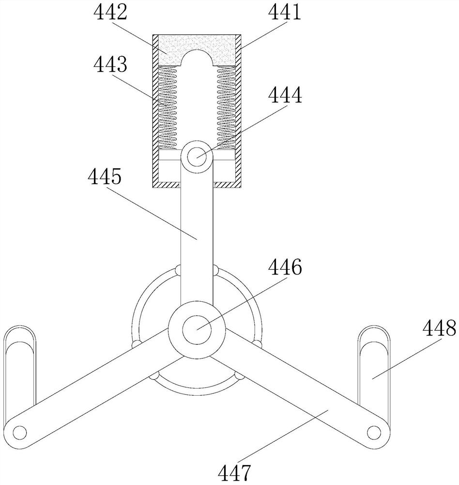
[0034] Wherein, the outer edge interference mechanism 45 includes a bracket 45a, a squeeze plate 45b, a telescopic hose 45c, a transmission pipe 45d, and an air bag mechanism 45e. An extruding plate 45b is arranged inside, and the lower end of the extruding plate 45b is provided with a telescopic hose 45c, and the lower end of the extruding hose 45c communicates with the inside of the airbag mechanism 45e through a transmission pipe 45d, and the extruding plate 45b is in an arc-shaped structure , matches the diameter of the sliding shaft 48a, which is beneficial for the sliding shaft 48a to be tightly squeezed with the extrusion plate 45b in the process of sliding down. Resilience is beneficial to squeeze and shrink the telescopic hose 45c to generate a certain air pressure.

[0035] Wherein, the air bag mechanism 45e includes a fixed ring e1, an air bag membrane e2, and a conduction tube e3, the interior of the fixe...


PUM


Abstract

The invention discloses a handling robot, the structure of which comprises a transmission belt, a motor, a support arm, a clamping hand, a rotating shaft, and a robot host. Stretch out the inside of the supporting plate shaft to support the center of the wafer, reduce the friction on the wafer, transport the wafer through the support arm, transport it to the detector, and use the electromagnetic block to absorb the adsorption block. Make the sliding axis at an inclined angle, so that the wafer falls on the inspection machine at an inclined angle inside the limit interference frame to prevent the thinner wafer from breaking. Through the conduction of the conduction tube, it is ensured that the airbag film inside each fixed ring is evenly bulged, so as to support the outer bottom of the wafer, reduce the friction on the surface of the wafer, and reduce the impact on the surface of the wafer. wear and tear.

Description

technical field [0001] The present invention relates to the field of robots, and more specifically, relates to a handling robot. Background technique [0002] The polysilicon crystal is melted and pulled out of the monocrystalline silicon ingot, and then cut into thin wafers. During the production process of the wafer, it is necessary to use a handling robot to transport the wafer to the inspection machine for inspection, but the handling During the process of handling the wafer by the robot, the wafer is clamped by the gripper hand on the handling robot, and the wafer is fixed on the gripper hand before handling and transferring. Since the thickness of the wafer is very thin and it is brittle and hard characteristics, during the process of clamping the wafer, the gripper hand produces a large friction force with the surface of the wafer, which is easy to cause wear on the surface of the wafer. There is a certain gap height between the bottom surface of the circle and the i...

Claims


Application Information

Patent Timeline
Patent Type & Authority Patents(China)
IPC IPC(8): B25J15/00
CPCB25J15/00
Inventor 胡坤宇
Owner 深圳市大族贝金装备有限公司
Why Eureka
Try Eureka