
An elevator lifting safety operation system

A technology for safe operation and elevators, applied in elevators, elevators in buildings, transportation and packaging, etc., can solve the problems of no vertical anti-pinch protection device, serious casualties, hidden safety hazards, etc., to achieve good teaching effect and guarantee Safety of life and effect of improving safety

Active Publication Date: 2021-10-22
佛山市华凯电梯工程有限公司
View PDF6 Cites 0 Cited by
  • Summary
  • Abstract
  • Description
  • Claims
  • Application Information

AI Technical Summary

Problems solved by technology

[0004] The purpose of the present invention is to solve the shortcoming that there is no vertical anti-pinch protection device in the prior art, which will inevitably cause great casualties and bring great safety hazards to people who take the elevator once such a situation occurs. An elevator safety operation system proposed

Method used


Image

  • An elevator lifting safety operation system
  • An elevator lifting safety operation system
  • An elevator lifting safety operation system

Examples


Embodiment 1

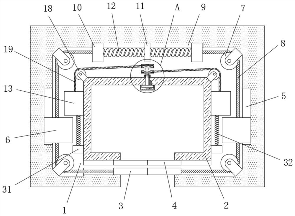
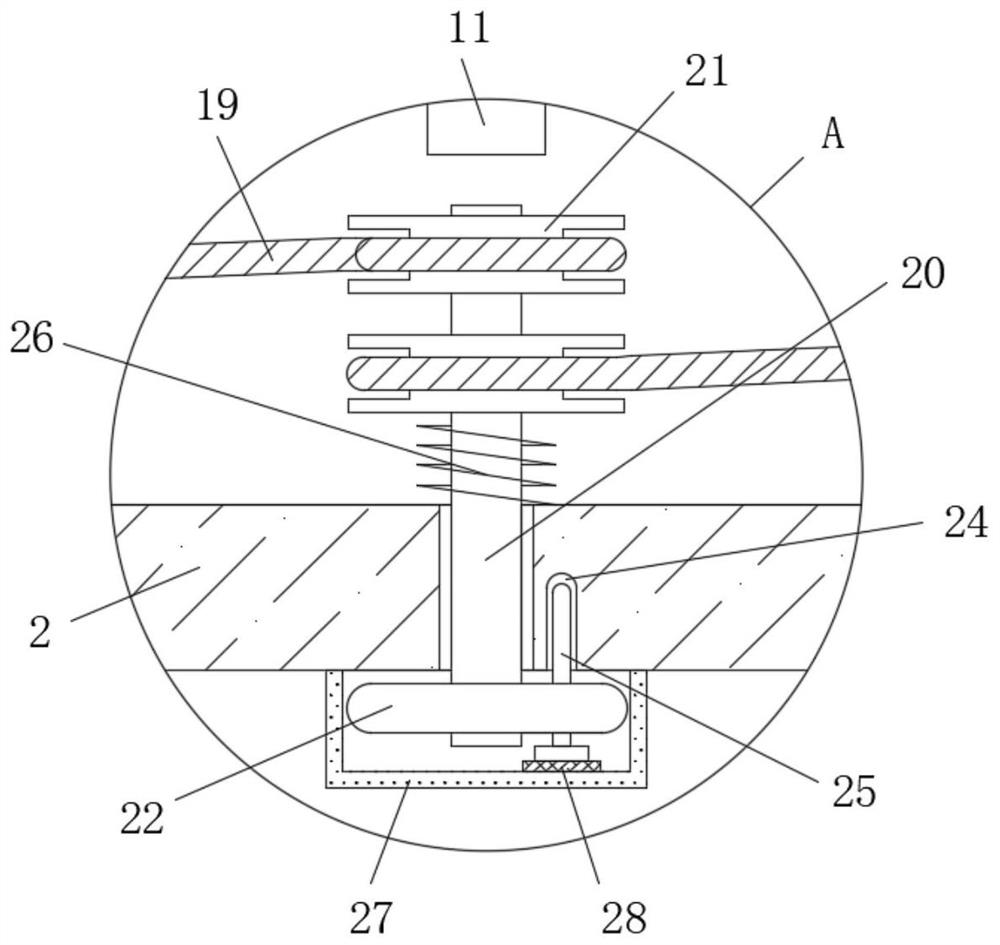
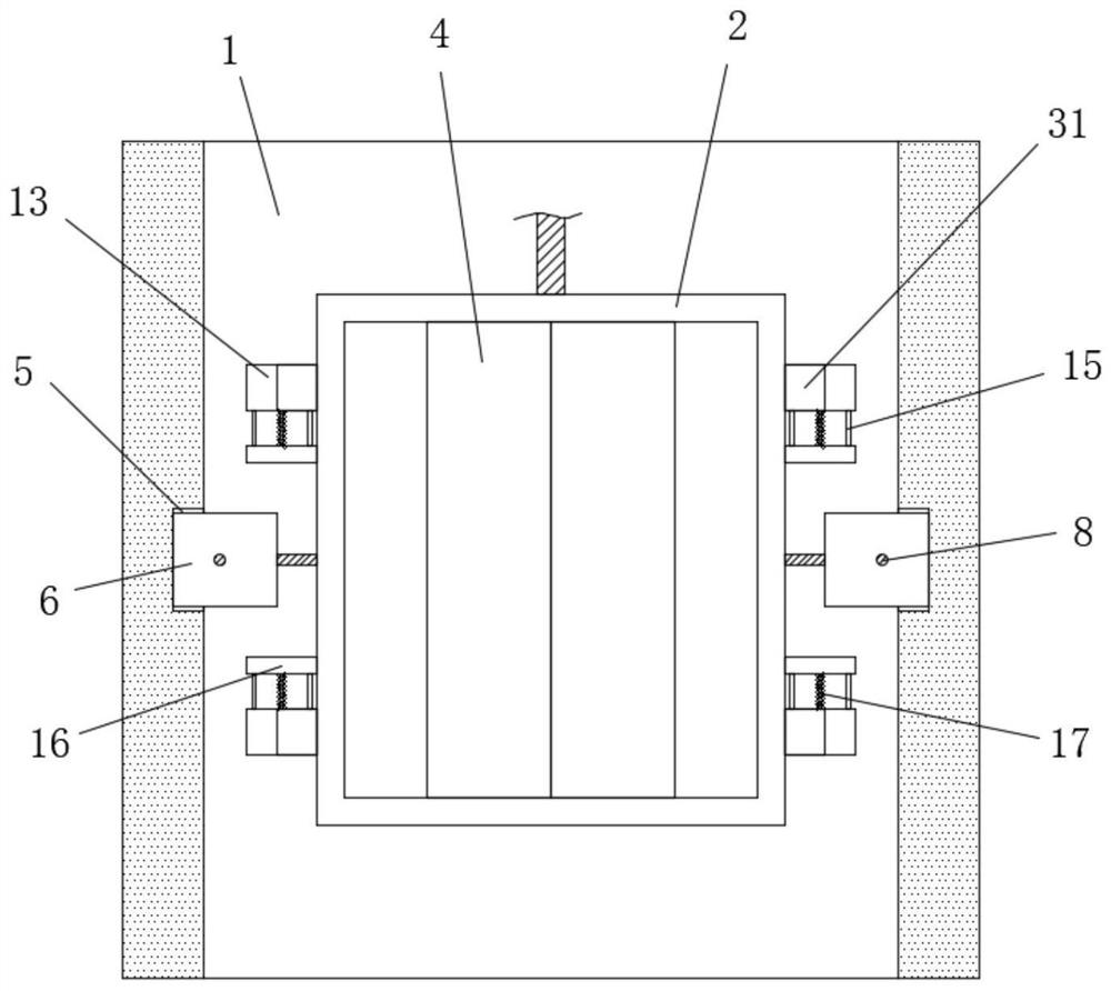
[0032] Refer Figure 1-9An elevator lifting and landing safety operation system includes a lift connection to the car 2 in the wellway 1, and one side of the wellway 1 is provided with a door door 3, and the side of the car 2 is provided with a parallel door 4 corresponding to the layer door 3. The inner wall of the wellway 1 is asymmetrically disposed with two first slide 5, and the two first slots 5 are symmetrically slided with two stops 6, and the two stoppers 6 are close to each other. The inside of the wellway 1 is extended, and the four corners of the inner wall of the wellway 1 are rotated, and the first guide wheel 7 is connected, and the inner wall of the outer portion of the wellway 1 away from the door 3 is provided with a second slider 9, and the second slide 9 is symmetrical. Sliding has two slider 10, and both of the two slider 10 extend to the inside of the wellway 1, and the block 6 is fixed to each other, and there is a first steel rope 8, two first steel rope 8 O...

Embodiment 2

[0034] Based on the first embodiment, the second chute 9 is fixedly connected to the first fixing block 11 between the two slider 10, and the first fixed block 11 is different from each other. A side of the block 10 is fixed to each other, and the same first tension spring 12 is attached, and the two sets of buffer components include the two sets of buffer components including the two sets of buffer assemblies. 13 The four angles of the four angles of each side is slid in the plurality of cylindrical grooves 14, and the sliding rod 15 is slidably connected, and the ends of the four sliding rods 15 on the same limit block 13 extends to the limit. The outer side of the block 13 is fixedly connected, and the same movable block 16 can be connected to the movable block 16 to a stable limit connection through the slider 15, and the movable block 16 is symmetrically fixed to each other. The buffer spring 17 can function on the movable block 16 to the cushioning movement by the buffer spr...


PUM


Abstract

The invention belongs to the technical field of elevator lifting systems, in particular to an elevator lifting safety operation system, aiming at the absence of vertical anti-pinch protection devices in the prior art, once such a situation occurs, it will inevitably cause great casualty accidents, causing serious accidents to passengers The people of the elevator bring great potential safety hazards. The following scheme is proposed now, which includes lifting and lowering the car connected in the shaft, one side of the shaft is provided with a landing door, and one side of the car is provided with a For the corresponding compartment door, two first sliding grooves are symmetrically arranged on the inner wall of the side of the shaft far away from each other. In the present invention, the stopper can be located between the two limiters by opening the landing door, so as to play a vertical role. To the effect of limit running protection, by pulling out the plunger to release the limit of the limit plate, the limit block can be moved to above the stop block, so as to prevent the elevator from falling and protect the passengers , greatly improving the safety of entering and exiting and taking the elevator.

Description

Technical field [0001] The present invention relates to the technical field of elevator lifting systems, and more particularly to an elevator lifting and safe operation system. Background technique [0002] The elevator refers to a permanent transportation device that serves a number of specific floors serving in the building, and the car runs at at least two columns perpendicular to a horizontal surface or a rigid rail movement of a rigid track movement of less than 15 ° with a lead profile tilt angle. The elevator is mainly treated, orientated , The car, the part of the electric control, and several parts of electric control. When working, the traction mechanism takes the lifting task. That is, the traction wheel drives the wire rope to do the round-trip movement, so that the car on both ends of the wire rope and the constraints of the respective guiding mechanism are perpendicular to the opposite movement, and the electrical control mechanism controls the car. The purpose of v...

Claims


Application Information

Patent Timeline
Patent Type & Authority Patents(China)
IPC IPC(8): B66B5/26B66B5/12B66B5/00B66B13/24B66B13/28B66B3/00
CPCB66B3/002B66B5/00B66B5/12B66B5/26B66B13/245B66B13/28
Inventor 李武戴灵李黎苹吴华盛
Owner 佛山市华凯电梯工程有限公司
Learn More