Mounting structure of building fabricated wall

An installation structure and assembly technology, which is applied in the direction of building components, building structures, construction, etc., can solve the problems of difficult assembly, no disassembly, and low production cost, and achieve the effects of wide application range, simple installation, and strong adaptability

Pending Publication Date: 2020-11-24
GOLD MANTIS FINE DECORATION TECH SUZHOU CO LTD
View PDF0 Cites 4 Cited by
  • Summary
  • Abstract
  • Description
  • Claims
  • Application Information

AI Technical Summary

Problems solved by technology

[0002] Some or all of the components of the building are prefabricated in the factory, and then transported to the construction site, and the components are assembled through reliable connections. The building is called a prefabricated building. The prefabricated building began to attract people's interest in the early 20th century. , and finally realized it in the 1960s. Britain, France, the Soviet Union and other countries first tried it. Due to the fast construction speed of prefabricated buildings and low production costs, they were quickly promoted all over the world. At present, prefabricated walls and light steel The connection method of the frame is mainly grouting connection, which has problems such as non-disassembly, long construction period, difficult assembly and difficult repair after the earthquake.

Method used


Image

  • Mounting structure of building fabricated wall
  • Mounting structure of building fabricated wall
  • Mounting structure of building fabricated wall

Examples


Embodiment Construction

[0028] The following will clearly and completely describe the technical solutions in the embodiments of the present invention with reference to the accompanying drawings in the embodiments of the present invention. Obviously, the described embodiments are only some, not all, embodiments of the present invention.

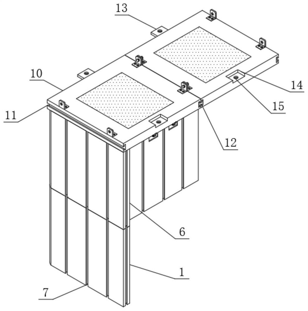
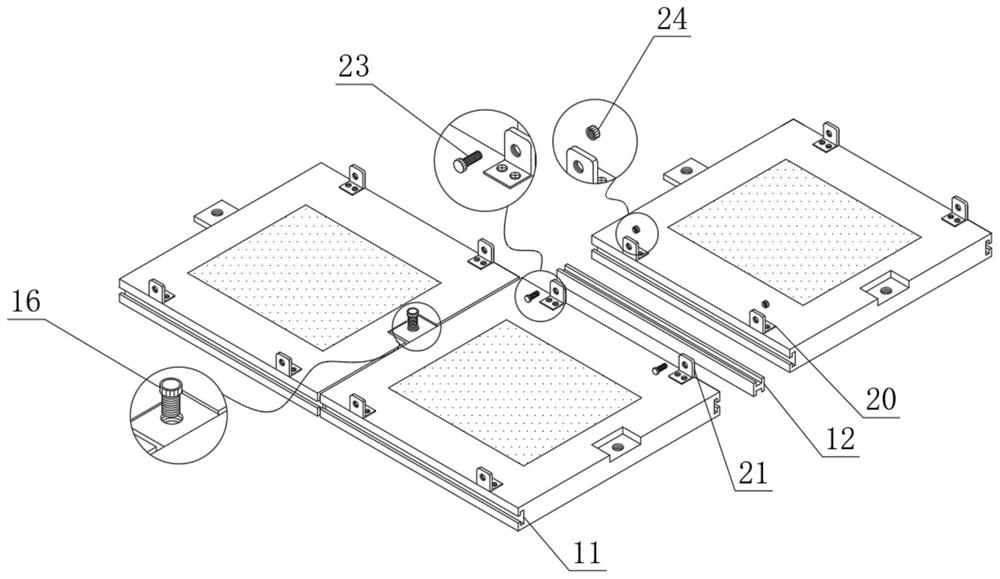
[0029] see Figure 1 to Figure 6 , the present invention provides a technical solution: an installation structure of a prefabricated building wall, including a first wall 1, the upper surface of the first wall 1 is sequentially provided with a limiting groove 2 and a block groove 3, and the limiting The inside of the groove 2 is movably connected with the limiting plate 4, and one side of the limiting plate 4 is provided with a second threaded hole 19, and the inside of the block groove 3 is movably connected with the first block 5, and one side of the limiting plate 4 is fixedly connected with a The second wall body 6, the upper surface structure of the second body ...


PUM


Abstract

The invention discloses a mounting structure of a building fabricated wall. The mounting structure comprises a first wall body, limiting grooves, clamping block grooves, limiting plates, first clamping blocks and a second wall body. First sliding grooves are formed in the two sides of the first wall body and in the two sides of the second wall body respectively, first sliding blocks are movably connected to one side of the first wall body and one side of the second wall body respectively, second sliding blocks are movably connected to the other side of the first wall body and the other side ofthe second wall body respectively, and the upper surface of the second wall body is movably connected with a third wall body. The mounting structure of the building fabricated wall has the main advantages that when the mounting structure is used, identical second wall bodies can be spliced multiple times through the limiting plates and the first clamping blocks; when identical first wall bodies are connected in parallel, the two sides of each first sliding block are clamped into the corresponding first sliding grooves respectively, so that fixing and connecting effects are achieved; and the identical first and second wall bodies can be spliced according to area requirements of different building construction.

Description

technical field [0001] The invention relates to the technical field of prefabricated installation equipment, in particular to an installation structure for a prefabricated building wall. Background technique [0002] Some or all of the components of the building are prefabricated in the factory, and then transported to the construction site, and the components are assembled through reliable connections. The building is called a prefabricated building. The prefabricated building began to attract people's interest in the early 20th century. , and finally realized it in the 1960s. Britain, France, the Soviet Union and other countries first tried it. Due to the fast construction speed of prefabricated buildings and low production costs, they were quickly promoted all over the world. At present, prefabricated walls and light steel The frame is mainly connected by grouting, which has problems such as non-disassembly, long construction period, difficult assembly, and difficult repa...

Claims


Application Information

Patent Timeline
IPC IPC(8): E04B1/343E04B1/61E04C2/30E04C2/32
CPCE04B1/34321E04B1/61E04B1/6116E04B1/6141E04B2001/6195E04C2/30E04C2/324
Inventor 何志伟陶金平杨启帆邱志强储媛园柴威李永峰徐忠亚隋阳刘小雨
Owner GOLD MANTIS FINE DECORATION TECH SUZHOU CO LTD
Why Eureka
Try Eureka