A kind of knocking equipment for indoor floor tiles
A technology for floor tiles and equipment, which is applied to the field of indoor floor tiles and the field of hammering equipment, can solve the problems of laboriousness and inconsistent hitting force of floor tiles, and achieve the effect of good effect and consistent hitting force.
- Summary
- Abstract
- Description
- Claims
- Application Information
AI Technical Summary
Problems solved by technology
Method used
Image

Examples
Embodiment 1
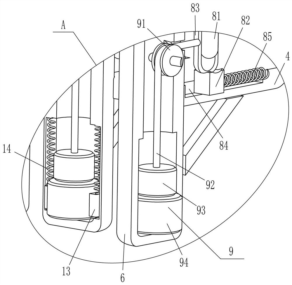
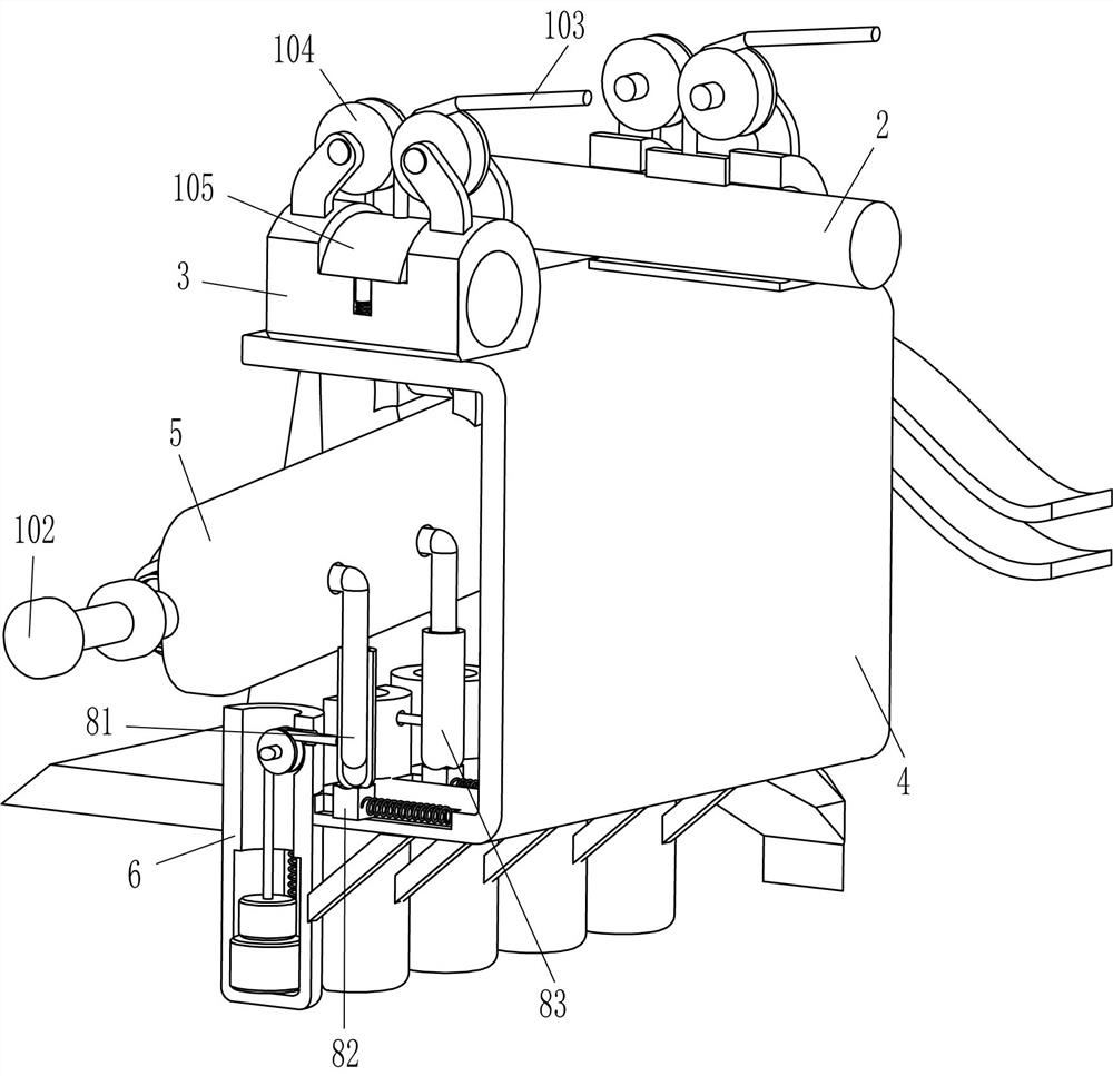
[0024] A kind of equipment for tapping after indoor floor tiles, such as Figure 1-Figure 4 As shown, it includes a base 1, an n-shaped rod 2, a sliding sleeve 3, a u-shaped plate 4, a hollow cylinder 5, a cylinder body 6, a steel ball 7, a trigger mechanism 8 and a knocking mechanism 9, and between the top of the base 1 on the left and right sides An n-shaped rod 2 is fixedly connected to the front and rear symmetrically, and a sliding sleeve 3 is installed on the n-shaped rod 2, and a u-shaped plate 4 is fixedly connected between the outer bottom of the sliding sleeve 3 on the front and rear sides, and the left side of the inner top of the u-shaped plate 4 A hollow cylinder 5 is hinged in the middle, and a steel ball 7 is arranged inside the hollow cylinder 5. A trigger mechanism 8 is provided between the inner bottom of the u-shaped plate 4 and the right side of the hollow cylinder 5. The trigger mechanism 8 cooperates with the steel ball 7, and the u-shaped plate 4 There a...
Embodiment 2
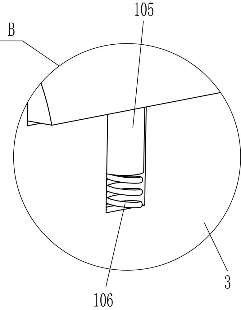
[0031] On the basis of Example 1, such as figure 1 , figure 2 with Figure 5 As shown, a swing mechanism 10 is also included, and the swing mechanism 10 includes a wave guide plate 101, a roller 102, a stay cord 103, a second guide wheel 104, an arc-shaped rubber plate 105 and a second spring 106, and the left and right side bases 1 A wave guide plate 101 is fixedly connected front and back symmetrically between the top, two n-shaped rods 2 are located between the wave guide plates 101 on the front and rear sides, and a roller shaft 102 is fixedly connected to the middle of the front and rear sides of the hollow cylinder 5, and the roller shaft 102 wears Cooperating with the wave guide plate 101, the left and right sides of the outer top of the sliding sleeve 3 are fixedly connected with the second guide wheel 104, and the sliding type embedded in the middle of the upper part of the sliding sleeve 3 is connected with an arc-shaped rubber plate 105, and the arc-shaped rubber ...
Embodiment 3
[0034] On the basis of embodiment 1 and embodiment 2, such as figure 2 with Figure 4 Shown, also comprise buffer block 11 and the 3rd spring 12, all are connected with the 3rd spring 12 in the front and rear sides of hollow cylinder 5, the 3rd spring 12 tail end is affixed with buffer block 11, buffer block 11 and steel ball 7 Cooperate.
[0035] Also comprise guide block 13 and the 4th spring 14, all slide type is provided with guide block 13 in cylinder body 6, front and rear both sides bottom, front and rear both sides guide block 13 inner surfaces are fixedly connected with large magnet 94 front and rear sides respectively, guiding A fourth spring 14 is connected between the top of the block 13 and the inside of the cylinder 6 .
[0036] When the steel ball 7 rolls forward to the maximum stroke or backward to the maximum stroke, the steel ball 7 contacts the buffer block 11, and due to the action of the fourth spring 14, the buffer block 11 buffers the steel ball 7. I...
PUM
 Abstract
Description
Claims
Application Information
 - R&D
- Intellectual Property
- Life Sciences
- Materials
- Tech Scout
- Unparalleled Data Quality
- Higher Quality Content
- 60% Fewer Hallucinations
Browse by: Latest US Patents, China's latest patents, Technical Efficacy Thesaurus, Application Domain, Technology Topic, Popular Technical Reports.
© 2025 PatSnap. All rights reserved.Legal|Privacy policy|Modern Slavery Act Transparency Statement|Sitemap|About US| Contact US: help@patsnap.com