Rotation shaft module of folding type device

A folding and pivoting technology, applied in the direction of pivot connection, etc., can solve the problem of affecting the overall thickness

Active Publication Date: 2020-10-02
JARLLYTEC CO LTD
View PDF8 Cites 0 Cited by
  • Summary
  • Abstract
  • Description
  • Claims
  • Application Information

AI Technical Summary

Problems solved by technology

[0002] The applicant once applied for an invention patent application entitled "Rotating Shaft Module of a Folding Device" (application number is Taiwan, China TW107113396 / CN201810371007.2, hereinafter referred to as the previous case 1), and one embodiment includes the first support piece, a pair of split shafts, a second support, a multi-axis shaft, and a third support for use with a flexible display, so that after the whole is folded into an S-shape, the second split shaft connected The first supporting member and the second supporting member can be closed, and will form an accommodating space inside the split rotating shaft to accommodate the curved area of ​​the flexible display, but in terms of the multi-axis rotating shaft, it is limited It is limited to keep a sufficient distance between the four shafts for the installation of other components (such as linkages, friction plates, linkage plates and stoppers, etc.), so after the overall folding, the multi-axis shaft There will be a gap between the connected second support and the third support. When the flexible display needs to be arranged on the same side of the three supports, the split shaft and the multi-axis shaft, the aforementioned spacing will affect the overall thickness

Method used


Image

  • Rotation shaft module of folding type device
  • Rotation shaft module of folding type device
  • Rotation shaft module of folding type device

Examples


Embodiment Construction

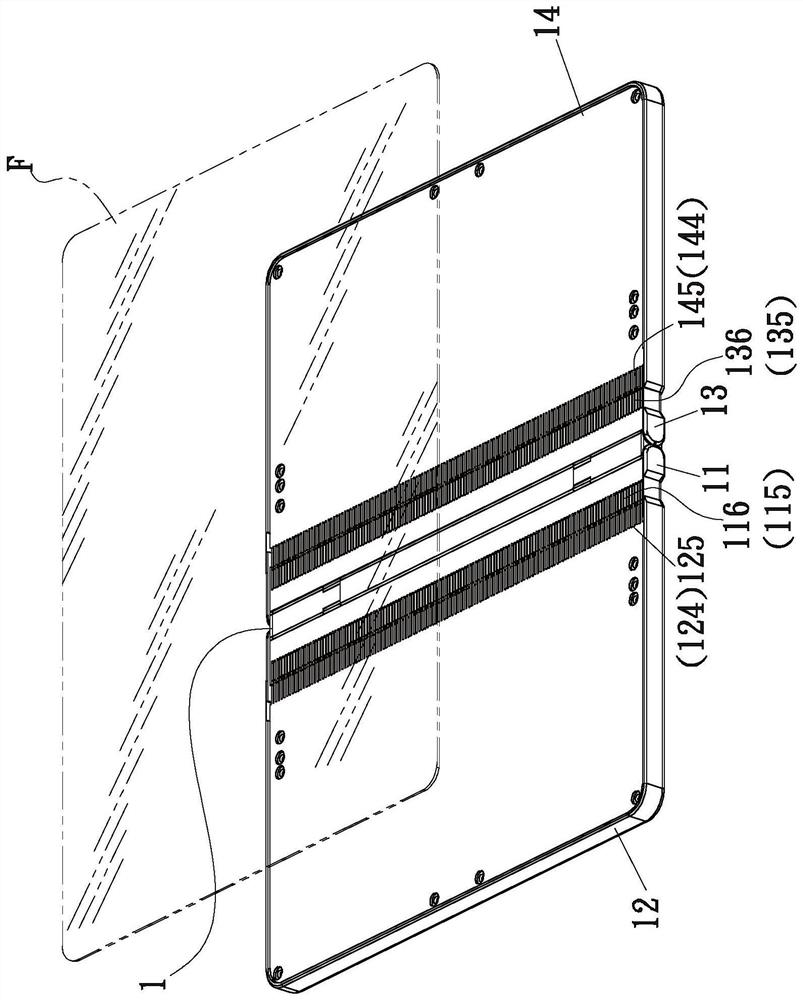
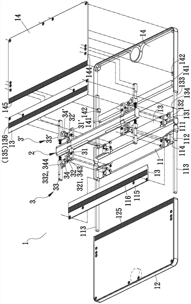
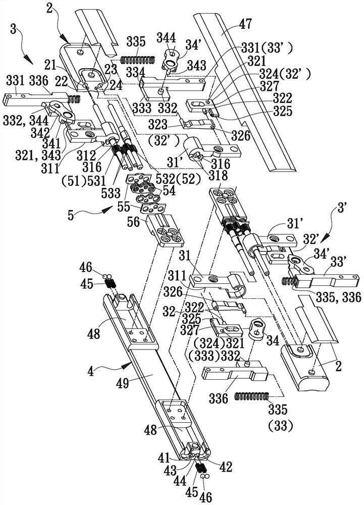
[0073] see Figure 1 to Figure 11 As shown, it is a preferred embodiment of the hinge module 1 of the present invention. The opposite ends of the hinge module 1 are respectively connected with a shell base, and a flexible display F is installed on the same side of the hinge module 1 and each shell base. The flexible display F can be turned into a folded or unfolded shape along with the two shell seats; the hinge module 1 includes a base 2 and two sliding mechanisms 3, 3', a sliding mechanism 3 Connecting one shell seat, another sliding mechanism 3' is connected to another shell seat, the sliding mechanism 3 and the other sliding mechanism 3' form a corresponding structure, and are symmetrically arranged at opposite ends of the base 2 An extension base 4 and at least one hinge device 5 accommodated in the extension base 4 are further provided between the two shell seats, and through one end of the sliding mechanism 3 (the first linkage 31) and an end of the other sliding mecha...


PUM


Abstract

The invention relates to a rotation shaft module of a folding type device. The rotation shaft module is connected with two shell bases, a matched flexibility display is relatively overturned into a folding shape or a non-folding shape accordingly, and each shell base comprises two shells capable of relatively sliding. The rotation shaft module comprises a base and two sliding mechanisms. One end portions of two transmission pieces of the sliding mechanisms are in pin joint with two pin joint parts at various ends of the base correspondingly, the sliding mechanisms are connected with the shellsthrough the relative ends of respective linkage pieces and various sliding pieces correspondingly, and guiding structures are arranged on the side edges and the end edges between every two shells; and through the transmission action of various middle transmission pieces between the linkage pieces and the sliding pieces and mutual guidance between the shells, the shell bases can stably stretch andcontract, the displacement path is utilized for compensating for the length change of the flexibility display after bending, and a bending part has a low curvature.

Description

technical field [0001] The invention relates to a hinge, in particular to a hinge module of a foldable electronic device. Background technique [0002] The applicant once applied for an invention patent application entitled "Rotating Shaft Module of a Folding Device" (application number is Taiwan, China TW107113396 / CN201810371007.2, hereinafter referred to as the previous case 1), and one embodiment includes the first support piece, a pair of split shafts, a second support, a multi-axis shaft, and a third support for use with a flexible display, so that after the whole is folded into an S-shape, the second split shaft connected The first supporting member and the second supporting member can be closed, and will form an accommodating space inside the split rotating shaft to accommodate the curved area of ​​the flexible display, but in terms of the multi-axis rotating shaft, it is limited It is limited to keep a sufficient distance between the four shafts for the installation...

Claims


Application Information

Patent Timeline
Patent Type & Authority Applications(China)
IPC IPC(8): F16C11/04
CPCF16C11/04
Inventor 许有村
Owner JARLLYTEC CO LTD
Why Eureka
Try Eureka