System and method for controlling traffic lights at expressway merging point

A technology for expressways and merging points, which is applied to the traffic control system of road vehicles, traffic control system, and traffic signal control to achieve the effect of reducing the incidence.

Active Publication Date: 2022-03-11
北京博研智通科技有限公司 +1
View PDF5 Cites 0 Cited by
  • Summary
  • Abstract
  • Description
  • Claims
  • Application Information

AI Technical Summary

Problems solved by technology

[0005] Therefore, the technical problem to be solved by the present invention is to overcome the prior art that only limits the flow of the ramp entering the main road, and ensures the maximum efficiency of the main road, so that when the traffic flow on the main road is small during peak hours, the ramp vehicles cannot enter the main road. road defects, thereby providing a lane light control system and method for express road merging points

Method used


Image

  • System and method for controlling traffic lights at expressway merging point
  • System and method for controlling traffic lights at expressway merging point
  • System and method for controlling traffic lights at expressway merging point

Examples


Embodiment 1

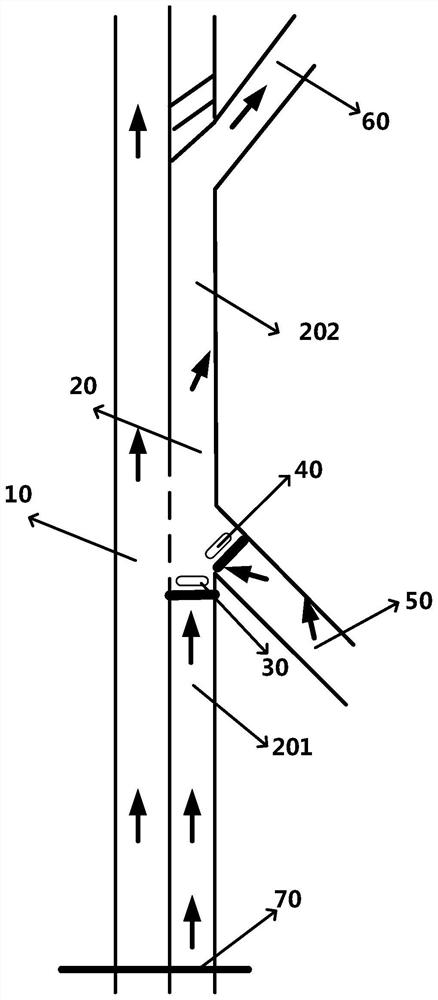
[0033] The embodiment of the present invention provides a lane light control system at a merging point on an expressway, which is applied to a specific application scenario of controlling the traffic flow entering or exiting a main road at a merging point or a diverging point in an expressway, such as figure 1 shown, including:

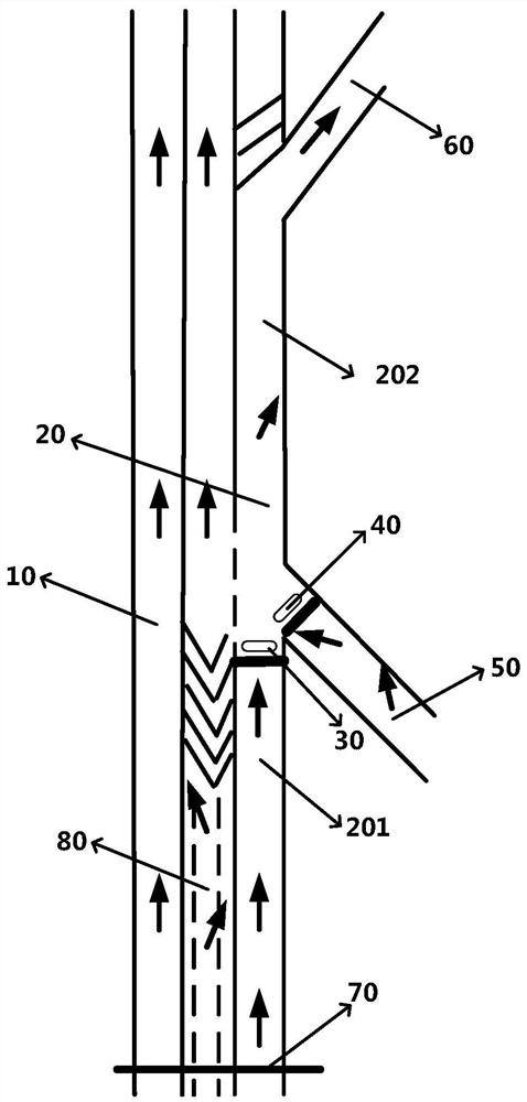
[0034] The first stop line is arranged on the downstream of the merging road section 201 of the expressway, and the first lane light 30 is arranged in front of the first stop line; the expressway includes: the first lane 10, the second lane 20, the ramp 50 and When exiting the ramp 60 , the second lane 20 includes a diverging road section 202 and a merging road section 201 .

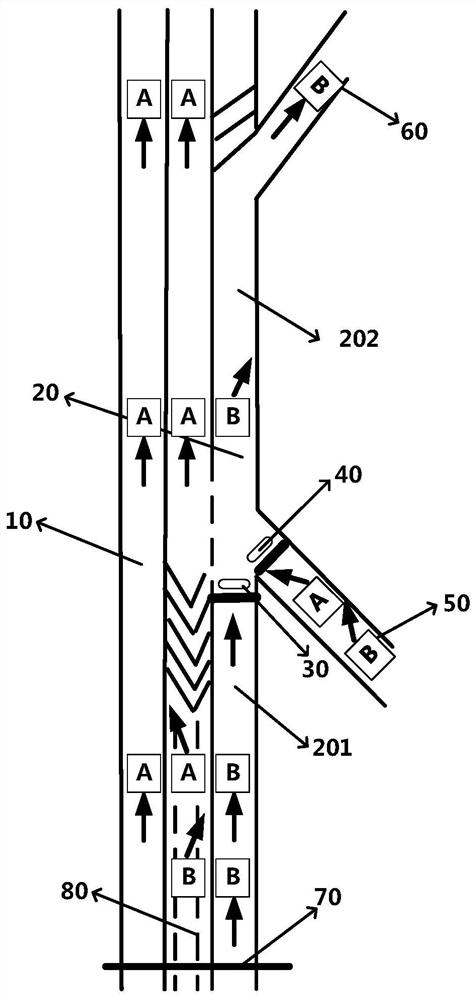
[0035] Exemplarily, the entering direction and the exiting direction of the expressway section are predetermined, and the motor vehicle enters from the entering direction and exits from the exiting direction, and the area passing through first is equal to the area passing throug...

Embodiment 2

[0056] An embodiment of the present invention provides a method for controlling lane lights at a confluence point of an expressway, which is applied to the system described in any of the above embodiments, such as Figure 4 As shown, the method includes:

[0057] Step S11: Obtain the driving information of each motor vehicle on the expressway, on-ramp, and off-ramp through the radar video tracking and detection device, wherein the driving information includes: position information at the current moment, speed information at the current moment, and The time information of arriving at the corresponding stop line, according to the above position information and speed information, correspondingly calculated time information of arriving at the designated position.

[0058] Step S12: According to the driving information, determine whether there is a motor vehicle on the merging road section and the on-ramp. In this embodiment, it can be judged on the merging road section on the seco...


PUM


Abstract

The present invention provides a lane light control system and method at the merging point of an expressway, wherein the system includes: a first stop line, which is set downstream of the merging section of the expressway, and a first lane is set in front of the first stop line Lights; Expressway includes: first lane, second lane, on-ramp and off-ramp, second lane includes diverging section and merging section, on-ramp intersects with second lane on the merging section, and off-ramp on diverging section It connects with the second lane; the second stop line is set at the junction of the on-ramp and the diversion road section, and the second lane light is set in front of the second stop line; the radar video tracking detection device is set on the expressway and the drive-in On the ramp, it is used to obtain the driving information of the motor vehicle; the lane light control device is communicated with the radar video tracking detection device, and is used to control the first lane light and / or the second lane light according to the driving information collected by the radar video tracking detection device .

Description

technical field [0001] The invention relates to the field of intelligent traffic control, in particular to a system and method for controlling lane lights at a confluence point of an expressway. Background technique [0002] The merging point and diverging point of the expressway are the source of periodic congestion on the expressway. How to accurately and effectively reduce the duration of the source of congestion caused by the merging point is a worldwide problem. [0003] Congestion of expressways during peak hours is common in large cities at home and abroad. It is generally believed that expressways are not controlled by signal lights and there should be no traffic jams. The expressway of the Fifth Ring Road has very serious traffic congestion. According to the analysis of survey data, most of the sources of congestion occur at the merging point or the diverging point. The management concept of dynamic merging and orderly diverging proposed by the first inventor requir...

Claims


Application Information

Patent Timeline
Patent Type & Authority Patents(China)
IPC IPC(8): G08G1/07G08G1/08
CPCG08G1/075G08G1/08
Inventor 姜廷顺李萌陆建王家捷朱林尹胜超郭娅明
Owner 北京博研智通科技有限公司
Why Eureka
Try Eureka