Eureka AIR delivers breakthrough ideas for toughest innovation challenges, trusted by R&D personnel around the world.

Gap eliminating device for gear and rack steering and damping and limiting method thereof

A technology of rack and pinion and steering gear, applied in the field of auto parts, can solve the problems of reducing the driving experience of vehicles, knocking, hidden dangers of driving safety, etc., so as to improve the pressing effect and stability, avoid tooth skipping, and avoid torque Effects of Attenuation Problems

Pending Publication Date: 2020-09-01
ZHEJIANG WANDA AUTOMOBILE DIRECTION MACHINE CO LTD
View PDF6 Cites 3 Cited by
  • Summary
  • Abstract
  • Description
  • Claims
  • Application Information

AI Technical Summary

Problems solved by technology

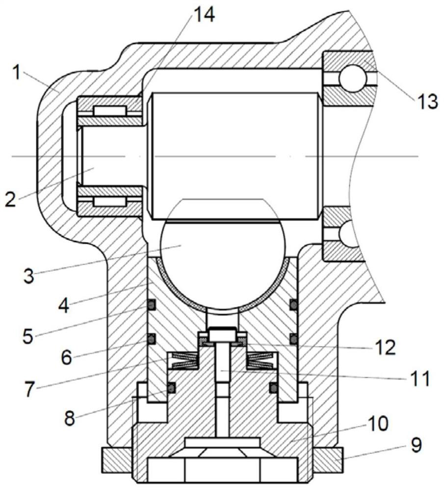
[0003] At present, the anti-backlash device used in the rack and pinion steering gear is mainly compressed by a coil spring. Since the compression force of the coil spring has a linear relationship with the compression amount, the compression force will decrease with the wear of the gear and rack, which is not conducive to Keep the performance of the product stable; at the same time, the existing steering gear product lacks a damping structure inside. When driving on a bumpy road, the vibration transmitted to the steering gear cannot be effectively attenuated, which will cause noise in the steering system and reduce the driving experience of the vehicle; In severe cases, problems such as knocking and tooth skipping may occur. In extreme cases, the steering system may be damaged and bring hidden dangers to driving safety.

Method used


Image

  • Gap eliminating device for gear and rack steering and damping and limiting method thereof
  • Gap eliminating device for gear and rack steering and damping and limiting method thereof
  • Gap eliminating device for gear and rack steering and damping and limiting method thereof

Examples


Embodiment Construction

[0031] The following will clearly and completely describe the technical solutions in the embodiments of the present invention with reference to the accompanying drawings in the embodiments of the present invention. Obviously, the described embodiments are only some, not all, embodiments of the present invention. The following description of at least one exemplary embodiment is merely illustrative in nature and in no way taken as limiting the invention, its application or uses. Based on the embodiments of the present invention, all other embodiments obtained by persons of ordinary skill in the art without creative efforts fall within the protection scope of the present invention.

[0032] The terminology used in the present invention is for the purpose of describing particular embodiments only and is not intended to limit the invention. For example, the following words indicating orientation or positional relationship such as "upper" and "lower" are only based on the orientatio...


PUM


Abstract

The invention discloses a gap eliminating device for a gear and rack steering and a damping and limiting method thereof. The device comprises a steering shell body, a gear and rack assembly and a supporting yoke, wherein the gear and rack assembly comprises a gear shaft rotationally supported on the steering shell body, a gear connected with the gear shaft and a rack engaged with the gear, a gap adjusting cavity is formed in the position, below the rack, of the steering gear shell body correspondingly, the supporting yoke is movably arranged in the gap adjusting cavity and abuts against the back surface of the rack, an adjusting screw plug is arranged at a lower opening of the gap adjusting cavity, a disc spring set is arranged between the adjusting screw plug and the supporting yoke, andthe disc spring set comprises at least two overlapped disc springs. According to the gap eliminating device for the gear and rack steering, the disc spring set is adopted as an elastic body, the discsprings can provide approximately consistent rigidity within a certain compression amount range through the arrangement mode that the two sets of disc springs are oppositely combined and connected inseries, and therefore the pressing force on the rack is kept unchanged basically after the gear and the rack are abraded, and the pressing effect and stability are improved.

Description

technical field [0001] The invention belongs to the technical field of auto parts, in particular to a steering gear. Background technique [0002] The steering gear is the reduction transmission device in the steering system, and generally has a 1-2 stage reduction transmission pair; according to the different structural forms of the transmission pair, the steering gear can be divided into many types. Currently, rack and pinion types are widely used in automobiles. There are several kinds of recirculating ball-rack and pinion type and recirculating ball-crank finger pin type. Among them, the rack and pinion steering gear is the most common type of steering gear; in the rack and pinion steering gear, the steering gear as the driving part of the transmission pair is installed in the housing and meshes with the horizontally arranged steering rack. A spring presses the rack against the steering pinion via a pressure piece to ensure backlash-free engagement. When working, the m...

Claims


Application Information

Patent Timeline
IPC IPC(8): F16H57/12F16F15/06B62D3/12
CPCF16H57/12F16F15/06F16F15/022B62D3/12F16H2057/127
Inventor 刘宇澄孙祖明高艳军
Owner ZHEJIANG WANDA AUTOMOBILE DIRECTION MACHINE CO LTD
Why Eureka
Eureka Blog
Learn More