


Quick Research
Generate reliable direction feasibility study reports for your R&D in just a few steps.

Technical Q&A
Discover and master advanced knowledge NOW. Basics, ideas, possibilities, all at once.

Find Solutions
As an expert in R&D theories, this can generate solutions to your technical problems instantly.

Evaluate Feasibility
Analyze your overall solution with one click, know your potential R&D risks in advance.

Monitor Landscape
Get weekly tech updates, stay abreast of the latest tech innovations and key insights.
Automatic locking device and using method
An automatic locking and locking block technology, applied in the direction of building locks, buildings, building structures, etc., can solve the problems of unable to meet the requirements of use, unable to achieve automatic locking, etc.
- Summary
- Abstract
- Description
- Claims
- Application Information
AI Technical Summary
Problems solved by technology
Method used
Image

Examples
Embodiment 1
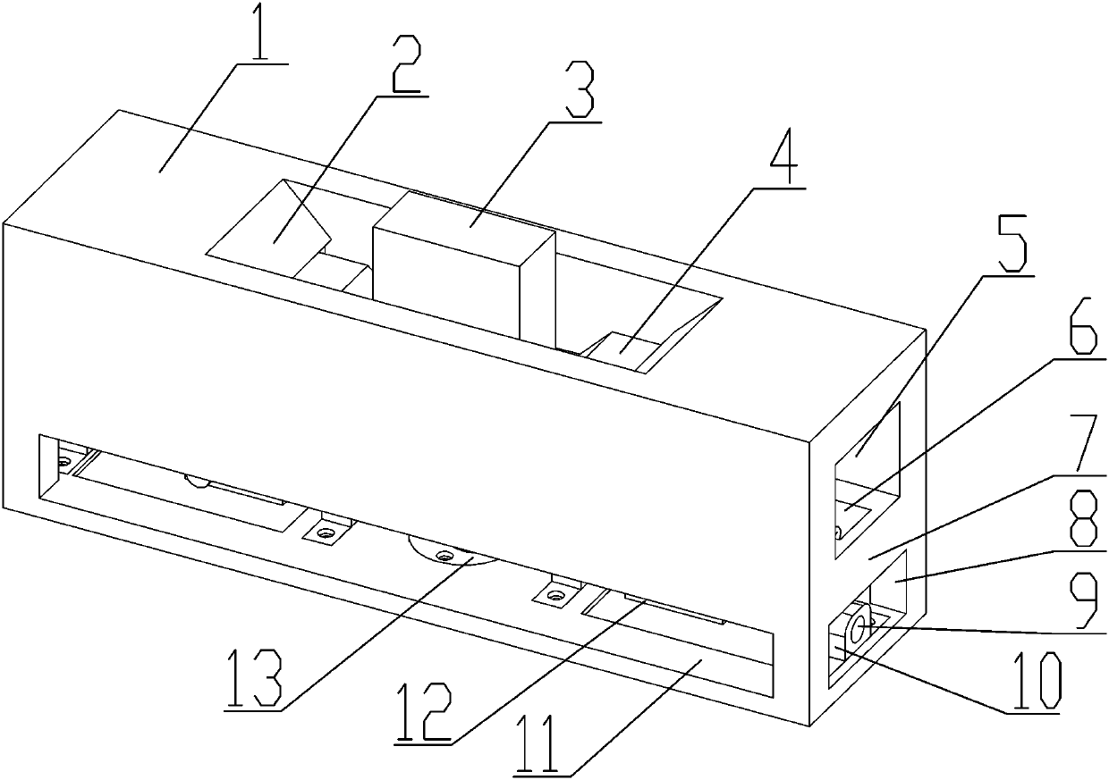
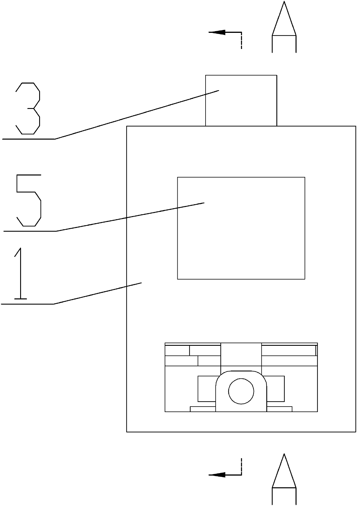
[0035] see Figure 1-6 , an automatic locking device, which includes an outer shell 1, the top of the outer shell 1 is processed with a tapered inlet 2; the middle part of the outer shell 1 is processed with a through hole 5 through its length direction, and the outer shell 1 The bottom layer of 1 is processed with a connecting rod mechanism installation groove 11, and an intermediate partition 23 is formed between the connecting rod installation groove 11 and the through hole 5, and the two sides of the intermediate partition 23 are symmetrically processed with chute 6, and the A locking block 21 is installed slidingly on the chute 6, and a reset mechanism is arranged between the locking block 21 and the outer shell 1, and the locking block 21 and the lock head block 3 form a hook locking fit; The locking block 21 cooperates with the synchronous link mechanism installed inside the connecting mechanism installation groove 11, and drives it to slide along the chute 6, so as to ...
Embodiment 2
[0045] The method of using the automatic locking device includes the following steps:
[0046] Step 1: The two locking blocks 21 are located at the innermost end of the chute 6 under the action of the return spring 19;
[0047] Step 2: Push the lock block 3 into the inside of the through hole 5 along the tapered inlet 2, the tapered structure 22 will push the locking block 21 to slide to both ends, and when it slides to the right end, the locking block 21 will Press-fit on the top of the tapered structure 22 to complete the locking of the lock block 3;
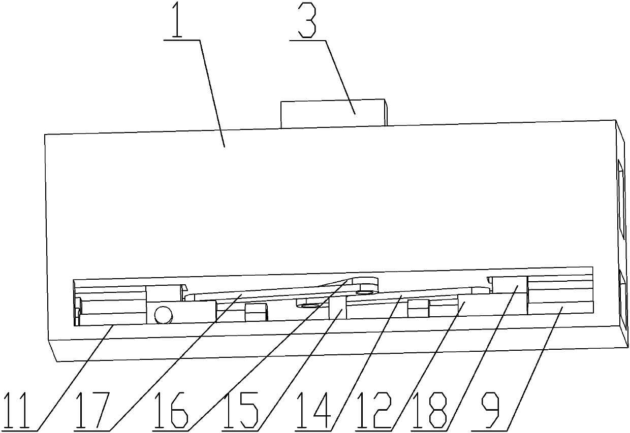
[0048] Step 3: When the lock needs to be released, drive the rotating shaft 15 to rotate through the power device, drive the rotating arm 16 to rotate through the rotating shaft 15, and then drive the first connecting rod 14 and the second connecting rod 17 synchronously through the rotating arm 16, and pass the first connecting rod The rod 14 and the second connecting rod 17 synchronously drive the slider 12 to slide along t...
PUM
 Abstract
Description
Claims
Application Information
 - R&D Engineer
- R&D Manager
- IP Professional
- Industry Leading Data Capabilities
- Powerful AI technology
- Patent DNA Extraction
Browse by: Latest US Patents, China's latest patents, Technical Efficacy Thesaurus, Application Domain, Technology Topic, Popular Technical Reports.
© 2024 PatSnap. All rights reserved.Legal|Privacy policy|Modern Slavery Act Transparency Statement|Sitemap|About US| Contact US: help@patsnap.com