Anti-slipping efficient cap screwing device
An anti-slip wire and high-efficiency technology, which is applied in the disassembly of threaded caps and finger-like grapples, etc., can solve the problems of failure, low success rate, slipping of hands, etc.
- Summary
- Abstract
- Description
- Claims
- Application Information
AI Technical Summary
Problems solved by technology
Method used
Image
Examples
Embodiment 1
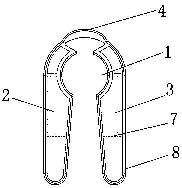
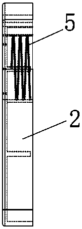
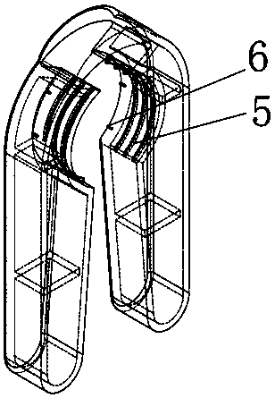
[0027] see Figure 1-3 , a high-efficiency capping device with anti-skid wire, including a capping device body, the capping device body is composed of a left handle 2 and a right handle 3 with an arc-shaped opening 1, the two handles are symmetrical to each other and the top passes through The first reinforcing structures 4 are connected together, and the arc-shaped opening 1 is provided with a screw structure 5 . The arc-shaped opening 1 is also provided with a vertical stripe structure 6, and the left handle 2 and the right handle 3 are also provided with a second reinforcement structure 7, the first and second reinforcement structures 7 are ribs, and the two handles are Also be provided with anti-slip sleeve 8, avoid slippage when holding by hand.
[0028] The bottle opening process of the present invention is as follows: use the two arc-shaped openings of the product of the present invention to block the bottle cap of the beverage, hold the beverage bottle body with one h...
Embodiment 2
[0030] Such as Figure 4 As shown, a high-efficiency capping device for anti-slip wires includes a capping device body. The capping device body is composed of two left handles 2 and right handles 3 with arc-shaped openings 1. The two handles are mutually connected to each other. The tops are symmetrical and connected to each other through the first reinforcement structure 4 , and the arc-shaped opening 1 is provided with a thread structure 5 . The arc-shaped opening 1 is also provided with a vertical stripe structure 6, the left handle 2 and the right handle 3 are also provided with a second reinforcement structure 7, the left handle 2 is provided with a self-locking block 9, and the right handle 3 A self-locking sleeve 10 is arranged on it, the self-locking block 9 is made of magnetic metal, and a magnetic element 11 is arranged inside the self-locking sleeve 10 .
[0031] The bottle opening process of the present invention is as follows: use the product of the present inven...
Embodiment 3
[0033] Such as Figure 5-7 As shown, the first half of this embodiment is the same as that of Embodiment 2, the difference being that the structures of the self-locking block 9 and the self-locking sleeve 10 are different, the self-locking block 9 includes a locking rod 12 and a threaded rod 13, and the locking rod 12 is penetrated with a Inner cavity 14, the end portion of lock bar 12 is hinged with two locking teeth 15, leaves gap between two locking teeth 15, is integrally formed with trapezoidal block 16 on locking tooth 15, and trapezoidal block 16 is positioned at inner cavity 14, and screw thread The rod 13 extends through the left handle 2 into the inner cavity 14 , and the self-locking sleeve 10 includes a locking hole 17 , and a locking block 18 matching the locking teeth 15 is arranged in the locking hole 17 .
[0034] When the self-locking block 9 and the self-locking sleeve 10 in this embodiment are opening the bottle, the threaded rod 13 is first rotated so that ...
PUM
 Abstract
Description
Claims
Application Information
 - R&D
- Intellectual Property
- Life Sciences
- Materials
- Tech Scout
- Unparalleled Data Quality
- Higher Quality Content
- 60% Fewer Hallucinations
Browse by: Latest US Patents, China's latest patents, Technical Efficacy Thesaurus, Application Domain, Technology Topic, Popular Technical Reports.
© 2025 PatSnap. All rights reserved.Legal|Privacy policy|Modern Slavery Act Transparency Statement|Sitemap|About US| Contact US: help@patsnap.com


