
Method for recovering stuck transmission mechanism

A technology of transmission mechanism and recovery method, which is applied in medical science, surgery, surgical fixation nails, etc., can solve the problems of gears and racks getting stuck, increase the risk of surgery, etc., and achieve the effect of releasing the stuck

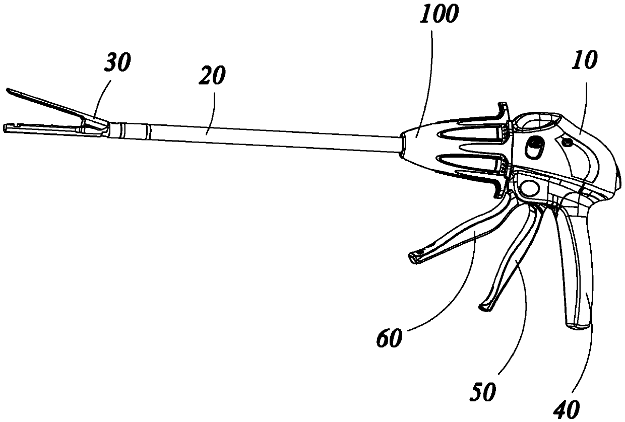
Pending Publication Date: 2020-06-16
FENGH MEDICAL CO LTD
View PDF21 Cites 0 Cited by
  • Summary
  • Abstract
  • Description
  • Claims
  • Application Information

AI Technical Summary

Problems solved by technology

However, during the process of withdrawing the knife, the gear and the rack are prone to jamming, which increases the risk of surgery

Method used


Image

  • Method for recovering stuck transmission mechanism
  • Method for recovering stuck transmission mechanism
  • Method for recovering stuck transmission mechanism

Examples


Embodiment Construction

[0033] Embodiments of the invention are described in detail below, examples of which are illustrated in the accompanying drawings.

[0034] The terms "first" and "second" are used for descriptive purposes only, and cannot be understood as indicating or implying relative importance or implicitly specifying the quantity of indicated technical features. Thus, the features defined as "first" and "second" may explicitly or implicitly include at least one of these features. In the description of the present invention, "plurality" means at least two, such as two, three, etc., unless otherwise specifically defined. "Several" means at least one.

[0035] The embodiments described below by referring to the figures are exemplary and are intended to explain the present invention and should not be construed as limiting the present invention.

[0036] The endocavity cutting stapler in the prior art generally includes a handle assembly, a shaft assembly extending longitudinally from the ha...


PUM


Abstract

The invention discloses a method for recovering a stuck transmission mechanism. The transmission mechanism comprises a first toothed piece, a second toothed piece and an abutting and pushing piece. The first toothed piece is meshed with the second toothed piece; the first toothed piece is adopted to drive the second toothed piece to move in a first direction, and after the first toothed piece andthe second toothed piece are engaged and clamped, recovery can be conducted through the following steps that S1, the abutting and pushing piece is adopted to drive the second toothed piece to move ina second direction, wherein the second direction is opposite to the first direction; and S2, the first toothed piece is adopted to drive the second toothed piece to move in the first direction. An operator controls the movement mode of the transmission mechanism through a steering piece and a limiting piece, and the situation that the transmission mechanism gets stuck in the working process can berelieved.

Description

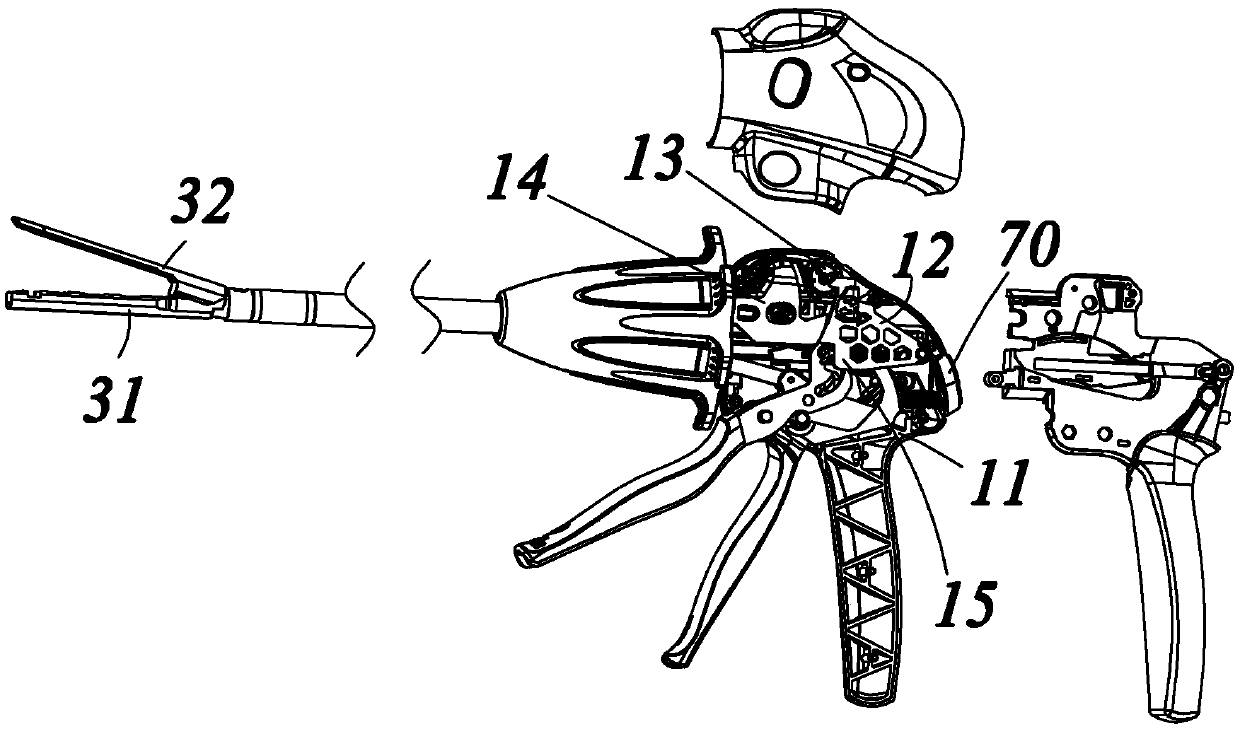
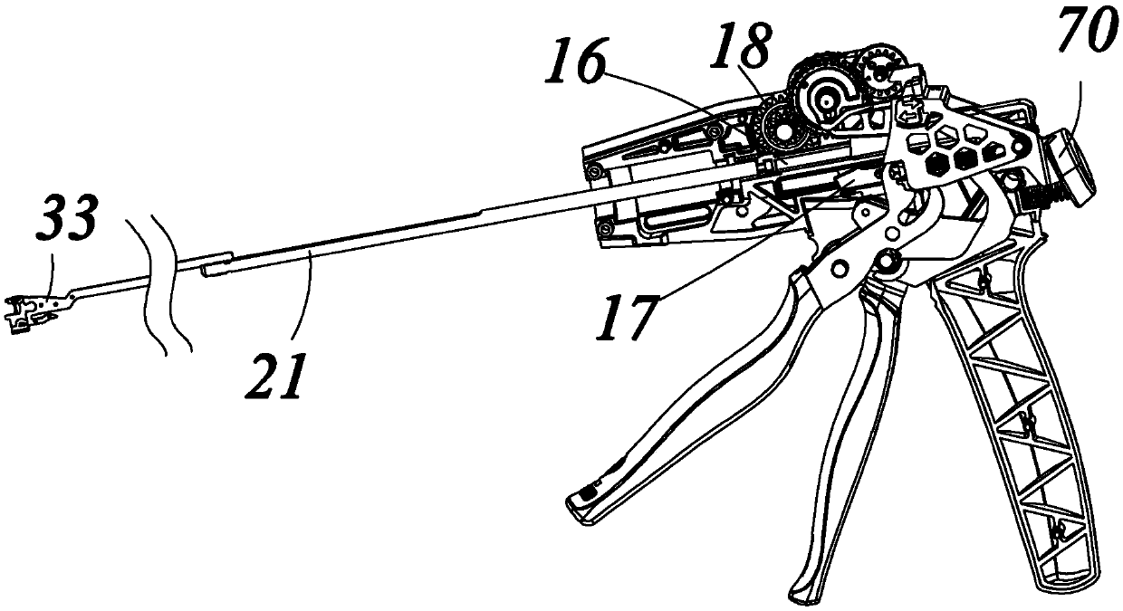
technical field [0001] The invention relates to a recovery method after a transmission mechanism is stuck. Background technique [0002] As we all know, endoluminal cutting staplers have been widely used in reconstructive operations such as stomach and colorectum. [0003] Existing endocavity cutting staplers generally include a handle assembly, a shaft assembly longitudinally extending from the handle assembly, and an end effector disposed at the distal end of the shaft assembly. A firing rod is arranged inside the shaft assembly. A cutting knife is arranged inside the end effector. The firing rod is connected with the cutting knife. A transmission mechanism is arranged inside the handle assembly, and the transmission mechanism includes a rack and a gear connected to each other. The rack is connected with the firing rod. The gear drives the rack to move backward. The rack drives the cutting knife to move backward through the firing rod, that is, to withdraw the knife....

Claims


Application Information

Patent Timeline
Patent Type & Authority Applications(China)
IPC IPC(8): A61B17/072
CPCA61B17/07207A61B2017/00367A61B2017/07271A61B2017/07278A61B2017/07285A61B2017/0046
Inventor 孙宝峰张志星
Owner FENGH MEDICAL CO LTD
Learn More