Cascade RF bus system

A bus system, cascaded technology, applied in the field of RF bus

Inactive Publication Date: 2020-06-02
SUZHOU CHEFUTONG INFORMATION TECHNOLOGY CO LTD
View PDF5 Cites 0 Cited by
  • Summary
  • Abstract
  • Description
  • Claims
  • Application Information

AI Technical Summary

Problems solved by technology

[0004] However, because RF transmission needs to consider impedance matching, it is impossible to directly perform serial connection such as 485 bus.

Method used


Image

  • Cascade RF bus system
  • Cascade RF bus system
  • Cascade RF bus system

Examples


Embodiment Construction

[0017] The present invention will be further described below in conjunction with the accompanying drawings and specific embodiments, so that those skilled in the art can better understand the present invention and implement it, but the examples given are not intended to limit the present invention.

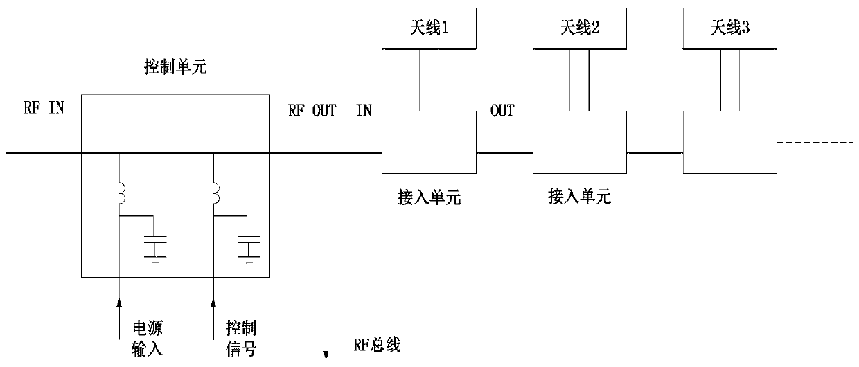
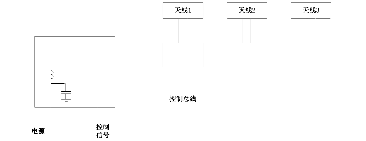
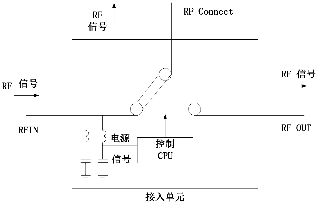
[0018] refer to Figure 1 to Figure 3 , a cascade RF bus system, comprising: a control unit, a plurality of access units and RF cables connecting the plurality of access units. Wherein, the control unit is responsible for providing power and control signals to each of the access units to determine which RF branch of the access unit communicates with the RF OUT of the control unit, and the access unit is responsible for receiving the instructions, and operate the RF switch according to the instructions, so that the input terminal RF IN of the access unit is connected to the RF Connect terminal or RF OUT terminal of the access unit; the RF cable connects the control unit to multiple...


PUM


Abstract

The invention discloses a cascaded RF (Radio Frequency) bus system. The cascaded RF bus system comprises a control unit, a plurality of access units and an RF cable coupling the plurality of access units; the control unit is responsible for providing a power supply and a control signal for each access unit to determine the RF branch of which access unit to be communicated with the RF OUT of the control unit; the access unit is responsible for receiving an instruction sent by the control unit and operating the RF switch according to the instruction, so that an input end RF IN of the access unitis connected to an RF Connect end or an RF OUT end of the access unit; the RF cable enables the control unit to be communicated with the plurality of access units in a cascading manner. The cascadedRF bus system has the advantages that the antenna can be connected to the RFID reader-writer like a connection bus, and therefore materials and construction cost are greatly saved.

Description

technical field [0001] The invention relates to the field of RF bus, in particular to a cascaded RF bus system. Background technique [0002] In RFID applications, in order to facilitate control or save costs, an RFID reader is sometimes connected to multiple antennas. [0003] The traditional technology has the following technical problems: [0004] However, because RF transmission needs to consider impedance matching, it is impossible to directly perform serial connection such as 485 bus. Contents of the invention [0005] The technical problem to be solved by the present invention is to provide a cascaded RF bus system. [0006] In order to solve the above technical problems, the present invention provides a cascaded RF bus system, comprising: a control unit, multiple access units and RF cables connecting the multiple access units. Wherein, the control unit is responsible for providing power and control signals to each of the access units to determine which RF branch...

Claims


Application Information

Patent Timeline
Patent Type & Authority Applications(China)
IPC IPC(8): G06K7/10
CPCG06K7/10297
Inventor 不公告发明人
Owner SUZHOU CHEFUTONG INFORMATION TECHNOLOGY CO LTD
Why Eureka
Try Eureka