Monitoring camera capable of shooting without dead angle

A technology for shooting surveillance and cameras, which is applied in the direction of supporting machines, mechanical equipment, machines/brackets, etc. It can solve the problems of blind spots in the shooting area of ​​surveillance cameras, no dead angle shooting, and monitoring loopholes.

Inactive Publication Date: 2020-05-19
苏州邦旺电子科技有限公司
View PDF0 Cites 1 Cited by
  • Summary
  • Abstract
  • Description
  • Claims
  • Application Information

AI Technical Summary

Problems solved by technology

[0002] The monitoring system is one of the most widely used systems in the security system. The more suitable construction site monitoring system on the market is a handheld video communication device. Video monitoring is now the mainstream, which involves a monitoring camera, and the existing monitoring cameras are not It has the function of shooting without dead angle, which leads to blind spots in the shooting area of ​​the surveillance camera, resulting in monitoring loopholes. For this reason, we propose a surveillance camera for shooting without dead angle

Method used


Image

  • Monitoring camera capable of shooting without dead angle
  • Monitoring camera capable of shooting without dead angle
  • Monitoring camera capable of shooting without dead angle

Examples


Embodiment Construction

[0015] The following will clearly and completely describe the technical solutions in the embodiments of the present invention with reference to the accompanying drawings in the embodiments of the present invention. Obviously, the described embodiments are only some, not all, embodiments of the present invention. Based on the embodiments of the present invention, all other embodiments obtained by persons of ordinary skill in the art without making creative efforts belong to the protection scope of the present invention.

[0016] In the description of the invention, it should be noted that, unless otherwise clearly specified and limited, the terms "installed", "set with", "connected", etc. should be understood in a broad sense, such as "connected", which may be a fixed connection, It can also be a detachable connection or an integral connection; it can be a mechanical connection or an electrical connection; it can be a direct connection or an indirect connection through an interm...


PUM


Abstract

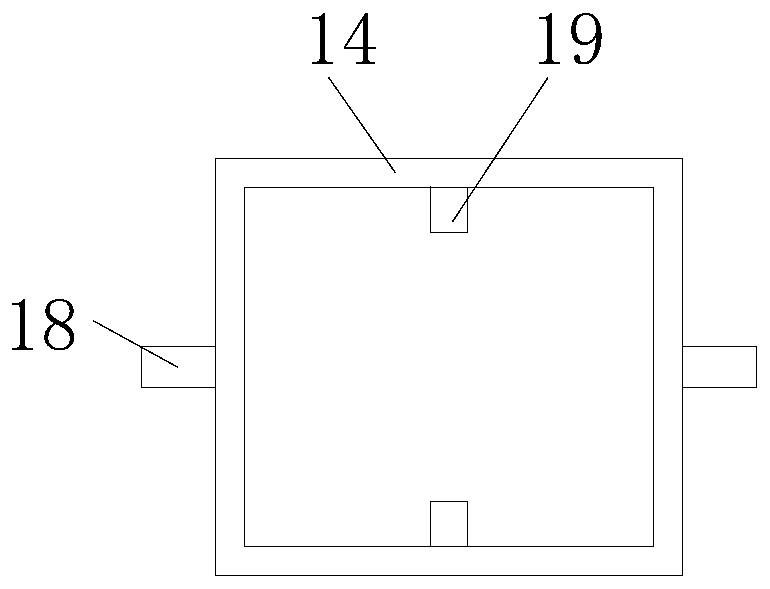
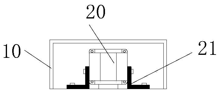
The invention discloses a monitoring camera capable of shooting without a dead angle. The monitoring camera comprises a supporting rod and a connecting plate, wherein a second motor is fixedly mountedat the top of the connecting plate through a fixing block; a first rotating rod is fixedly connected to the output end of the second motor; a third connecting block is fixedly connected to the bottomof the first rotating rod; the camera is movably connected to the lower end of the third connecting block through a second rotating rod; a second tooth groove is formed in the outer surface of the lower end of the second rotating rod; and a second gear is connected to the right end of the top of the camera. According to the monitoring camera, the first rotating rod, the third connecting block, the camera and the second rotating rod are arranged, a first motor is started to work through an external controller and drives a first gear to rotate, the first gear drives a rotating shaft to rotate through a first tooth groove, and the rotating shaft drives the connecting plate to rotate through a second connecting block, so that the problem is solved that dead zones generated in the shooting area of the monitoring camera cause loopholes in monitoring, as an existing monitoring camera does not have the function of shooting without the dead angle.

Description

technical field [0001] The invention relates to the technical field of monitoring, in particular to a monitoring camera for shooting without dead angles. Background technique [0002] The monitoring system is one of the most widely used systems in the security system. The more suitable construction site monitoring system on the market is a handheld video communication device. Video monitoring is now the mainstream, which involves a monitoring camera, and the existing monitoring cameras are not It has the function of shooting without dead angle, which leads to blind spots in the shooting area of ​​the surveillance camera, resulting in monitoring loopholes. Therefore, we propose a surveillance camera for shooting without dead angle. Contents of the invention [0003] The object of the present invention is to provide a surveillance camera for shooting without dead angles, so as to solve the problems raised in the above-mentioned background technology. [0004] In order to ac...

Claims


Application Information

Patent Timeline
Patent Type & Authority Applications(China)
IPC IPC(8): F16M11/12F16M11/18F16M11/22
CPCF16M11/043F16M11/12F16M11/18F16M11/22
Inventor 郭永红
Owner 苏州邦旺电子科技有限公司
Why Eureka
Try Eureka