A stereo rotary speaker

A sound and stereo technology, applied in the field of stereo rotary sound, can solve the problem of not feeling overweight bass, and achieve the effect of good entertainment and increased interest.

Active Publication Date: 2021-04-06
深圳市极客智造科技有限公司
View PDF4 Cites 0 Cited by
  • Summary
  • Abstract
  • Description
  • Claims
  • Application Information

AI Technical Summary

Problems solved by technology

[0002] Entertainment and leisure places usually provide wonderful performances by bands or singers. With high-end audio equipment, the atmosphere and entertainment effects are increased. However, traditional audio equipment has a fixed position and a fixed angle, so that people who are close to the audio can always hear louder sounds. And then cause discomfort, people who are far away from the sound can not feel the atmosphere of the subwoofer, and the above situation can be improved on the basis of the above or by using the sound that can change in multiple degrees of freedom in the space

Method used


Image

  • A stereo rotary speaker
  • A stereo rotary speaker
  • A stereo rotary speaker

Examples


specific Embodiment approach 1

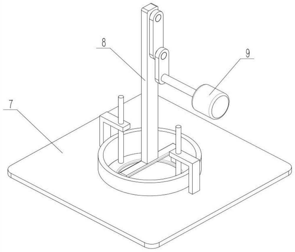
[0032] Such as Figure 1-11 As shown in the figure, a stereo rotary sound system includes a middle part 1, a main beam 2, a moving beam 3, a push-pull part 4, an audio case 5, a reciprocating trigger mechanism 6, an audio bottom case 7, a subwoofer 8 and a failure mechanism 9, The lower end of the middle part 1 is rotationally connected with the right end of the main beam 2, the left end of the main beam 2 is rotationally connected with the right end of the moving beam 3, the right end of the push-pull part 4 is fixedly connected with the main beam 2, and the left end of the push-pull part 4 is connected with a transmission. In the moving beam 3, the upper end of the sound housing 5 is rotationally connected with the left side of the moving beam 3, the reciprocating trigger mechanism 6 is connected with the left side of the lower end of the moving beam 3, the reciprocating trigger mechanism 6 is connected with the sound housing 5 through transmission, and the sound The lower e...

specific Embodiment approach 2

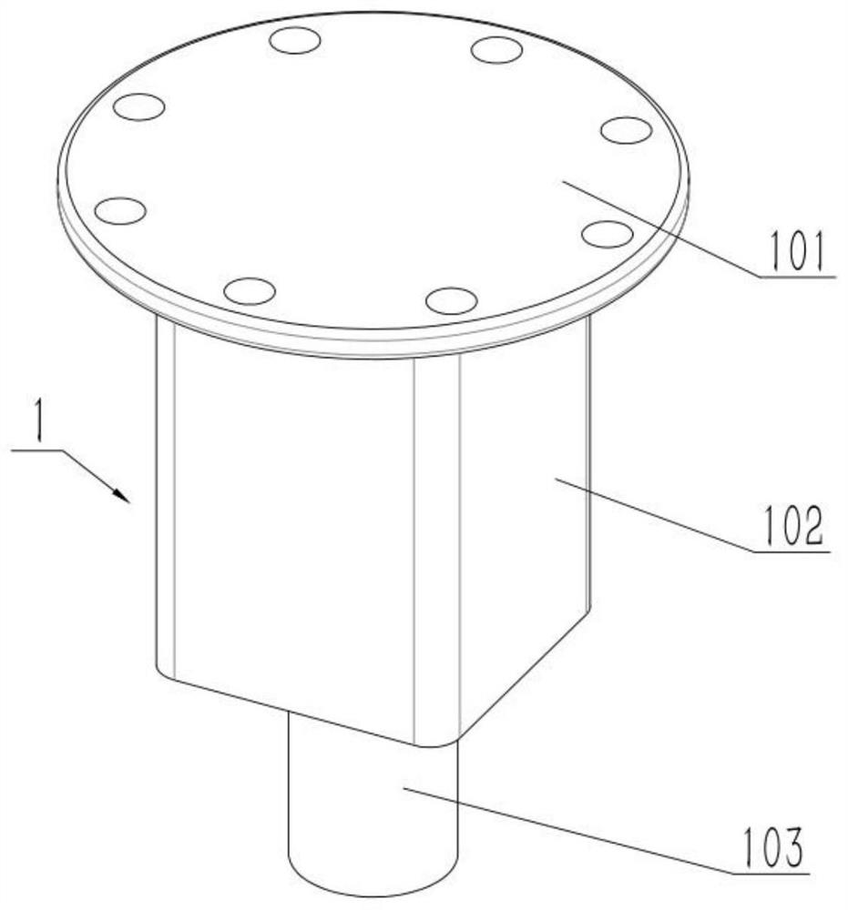
[0034] Such as Figure 1-11 As shown, the middle rotor 1 includes a fixed base 101 , a motor I 102 and a main shaft 103 , the lower end of the fixed base 101 is fixedly connected to the motor I 102 , and the output shaft of the motor I 102 is fixedly connected to the main shaft 103 . Fix the fixing seat 101 on the top, such as the roof or other shelves, and its position should be located in the center of the user's entertainment space, start the motor I102, the output shaft of the motor I102 drives the main beam body 201 to rotate, and then the main beam 2 can rotate.

specific Embodiment approach 3

[0036] Such as Figure 1-11 As shown, the main beam 2 includes a main beam body 201, a frame 202 and a short shaft 203, the middle part of the main beam body 201 is provided with a frame 202, and the left end of the main beam body 201 is fixedly connected to the short shaft 203; the main shaft 103 The lower end of the rotatably connected to the right side of the main beam body 201. The rotation of the main beam 2 can drive other parts to move synchronously with it.


PUM


Abstract

The invention relates to the field of sound, more specifically a stereo rotary sound. Including the middle part, the main beam, the moving beam, the push-pull part, the sound shell, the reciprocating trigger mechanism, the sound bottom shell, the subwoofer and the failure mechanism, it can be achieved by using the multi-degree-of-freedom change of the sound shell and the subwoofer. The alternation of disengagement produces sound surround far and near changes, repeated aggravation and reduction of sound, repeated effect and failure of subwoofer, and increases the interest of special changes, making the entertainment effect of audio better.

Description

technical field [0001] The invention relates to the field of sound, more specifically a stereo rotary sound. Background technique [0002] Entertainment and leisure places usually provide wonderful performances by bands or singers. With high-end audio equipment, the atmosphere and entertainment effects are increased. However, traditional audio equipment has a fixed position and a fixed angle, so that people who are close to the audio can always hear louder sounds. And then produce discomfort, people who are far away from the sound can not feel the atmosphere of the subwoofer, and the above situation can be improved by using the sound that can change in multiple degrees of freedom on the basis of the above or alone. Contents of the invention [0003] The object of the present invention is to provide a stereo rotary sound system, which can perform multi-degree-of-freedom rotation adjustment and increase the entertainment effect. [0004] The purpose of the present invention...

Claims


Application Information

Patent Timeline
Patent Type & Authority Patents(China)
IPC IPC(8): H04R1/02H04R5/02
CPCH04R1/02H04R1/025H04R5/02
Inventor 刘禹希
Owner 深圳市极客智造科技有限公司
Why Eureka
Try Eureka