Rotatable dustproof insulator

A technology of insulators and rotating sleeves, applied in the direction of insulators, electrical components, circuits, etc., can solve the problems of inability to deal with rainwater and dust, and achieve good results

Inactive Publication Date: 2020-03-27
HUBEI UNIV OF TECH
View PDF1 Cites 3 Cited by
  • Summary
  • Abstract
  • Description
  • Claims
  • Application Information

AI Technical Summary

Problems solved by technology

A rotary three-proof insulator in the above-mentioned patent has the following disadvantages: the device can shake off the dust and rainwater on the surface of the insulator through the rotation of the insulator, but it cannot handle the rainwater and dust at the connection between the line and the insulator, and cannot solve the problem. above question

Method used


Image

  • Rotatable dustproof insulator
  • Rotatable dustproof insulator
  • Rotatable dustproof insulator

Examples


Embodiment 1

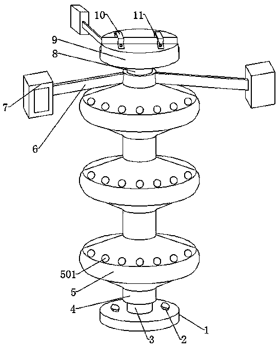
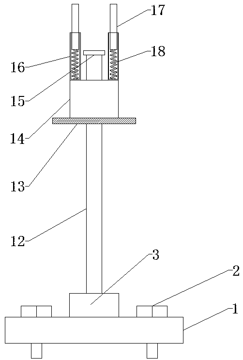
[0029] refer to Figure 1-5 , a rotatable dust-proof insulator, including a base 1, a fixed block 3 is welded in the middle of the top end of the base 1, a rotating sleeve 4 is provided on the outer wall of the fixed block 3, and a fixed block 3 is welded on the top end of the fixed block 3. A reciprocating screw rod 12, the outer cover of the reciprocating screw rod 12 is provided with a rotating block 14, the bottom end of the rotating block 14 is welded with a rubber plate 13, and the rubber plate 13 is slidably connected with the inner wall of the rotating sleeve 4. The top end of the rotating sleeve 4 is provided with a first through hole, the rotating sleeve 4 is rotatably connected with a connecting sleeve 8 at the first through hole, and the top end of the connecting sleeve 8 is welded with a fixed disk 9 .

[0030] In the present invention, the top of the rotating block 14 is welded with two fixed cylinders 16, and the tops of the two fixed cylinders 16 are provided w...

Embodiment 2

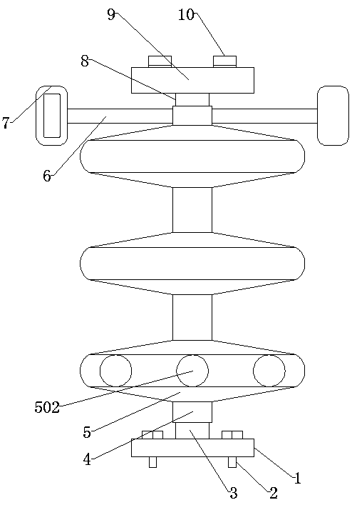
[0038] refer to Image 6 , a rotatable dust-proof insulator. Compared with Embodiment 1, in this embodiment, in order to have a certain range of motion between the line and the insulator, the bottom ends of both sides of the connecting sleeve 8 are welded with clamping blocks 19, Both sides of the top of the inner wall of the rotating sleeve 4 are provided with slideways, the block 19 is slidably connected with the rotating sleeve 4 on the slideway, and a second spring is welded between the bottom end of the connecting sleeve 8 and the rotating sleeve 4 20 , the block 19 can slide on the inner wall of the rotating sleeve 4 , and the connecting sleeve 8 can move within a certain range through the second spring 20 .

[0039] When in use, the device is fixed on the wire rack by the base 1 and the first screw 2, and the circuit can be fixed in the strip groove of the fixed disk 9 by the fixed piece 10 and the second screw 11. The plate 7 can drive the connecting rod 6 to rotate, ...


PUM


Abstract

The invention belongs to the technical field of power distribution equipment, in particular to a rotatable dustproof insulator. The problem that dust and rainwater accumulated at the joint of an insulator and a line are difficult to remove is solved. The insulator includes a base, a fixing block is fixedly connected to the middle of the top end of the base. The outer wall of the fixing block is sleeved with a rotating sleeve. The top end of the fixing block is fixedly connected with a reciprocating screw rod; the reciprocating lead screw is sleeved with a rotating block, the bottom end of therotating block is fixedly connected with a rubber plate, the rubber plate is slidably connected with the inner wall of a rotating sleeve, a first through hole is formed in the top end of the rotatingsleeve, the rotating sleeve is rotatably connected with a connecting sleeve at the first through hole, and the top end of the connecting sleeve is fixedly connected with a fixing disc. The rotating sleeve rotates to drive the rubber plate to move up and down to do piston motion, so that an air blowing effect can be achieved, dust and rainwater at the position where a circuit and the device are fixed can be blown away, and a better effect is achieved.

Description

technical field [0001] The invention relates to the technical field of power distribution equipment, in particular to a rotatable dustproof insulator. Background technique [0002] At present, the insulators of high-voltage overhead lines in the power grid are divided into two types: pillar type and suspension type, which play the role of fixing and insulating the line. Now, the measures to improve the anti-flashover ability of insulators are mainly from the three aspects of insulator materials, cleaning, and hydrophobic coatings. , It needs to consume a lot of manpower, material resources and financial resources. The existing insulators have weak waterproof and dustproof capabilities, especially the connection between lines and insulators, which affects the safety of power transmission of cables. [0003] After searching, the Chinese patent application number is 201310252803.1, which discloses a rotary three-proof insulator, including a fixed handle, a suspension shaft, an ...

Claims


Application Information

Patent Timeline
Patent Type & Authority Applications(China)
IPC IPC(8): H01B17/38
CPCH01B17/38
Inventor 汪繁荣李渊周子槊彭禄向堃
Owner HUBEI UNIV OF TECH
Why Eureka
Try Eureka