Container
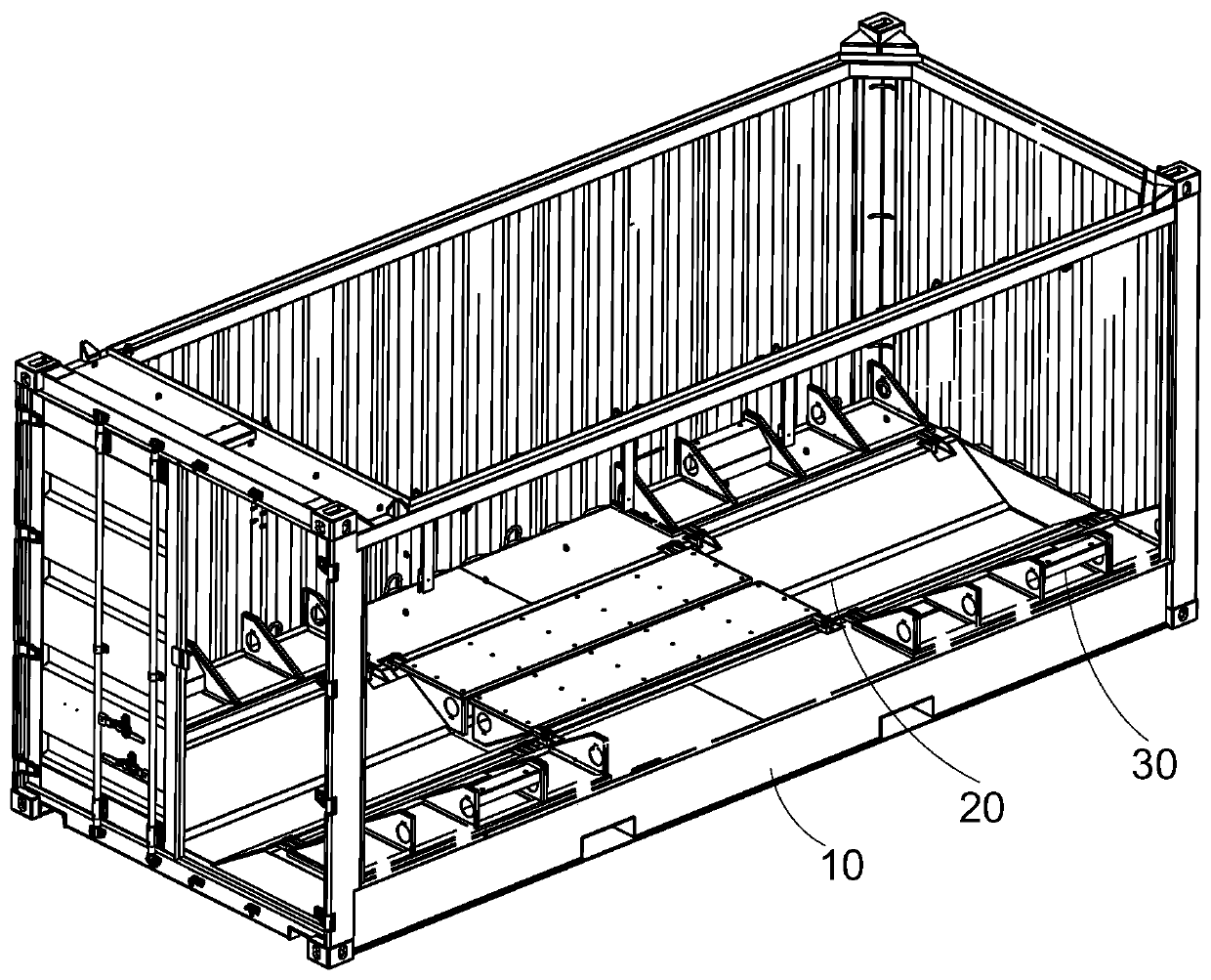
A container and support plate technology, applied in the field of containers, can solve the problems of increasing manufacturing and transportation costs, increasing the height and size of the chassis 10, and large space, and achieve the effect of low manufacturing and transportation costs and small height and size
- Summary
- Abstract
- Description
- Claims
- Application Information
AI Technical Summary
Problems solved by technology
Method used
Image
Examples
no. 1 approach
[0053] A preferred embodiment of the present invention provides a container. The container can be used to transport cylindrical goods (such as coiled steel belts).
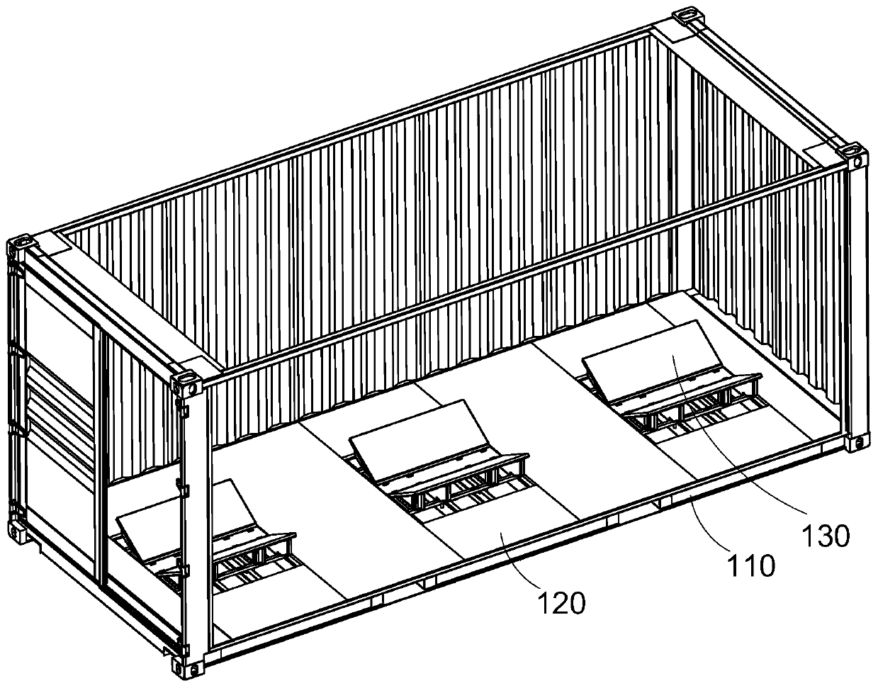
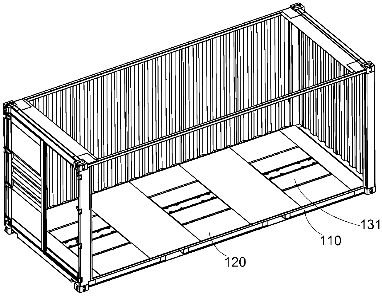
[0054] Such as Figure 2 to Figure 9 As shown, the container includes a chassis 110, a roof, end walls and side walls. The bottom frame 110 , the top plate, the end walls and the side walls enclose the inner space of the container for accommodating goods to be transported. A floor 120 is laid on the chassis 110 . The chassis 110 includes bottom beams. The bottom beam may be a bottom beam 111 .
[0055]The container also includes a plurality (for example, three) of cargo support assemblies arranged at intervals along the length direction of the container. In the width direction of the container, the cargo support assembly is arranged at a substantially middle position of the underframe 110 . The cargo support assembly is used to support the aforementioned cylindrical cargo. Each cargo support assembly may in...
no. 2 approach
[0071] The floor 220 and the support member 230 of this embodiment are substantially the same as those of the first embodiment. Such as Figure 11 As shown, a plurality of cargo support assemblies are spaced apart along the length of the container. The length direction of the cargo support plate extends along the width direction of the container. One side of the cargo support plate in the width direction is pivotally connected to the underframe 210 , and at this time, the pivot axis of the cargo support plate is substantially parallel to the width direction of the container. At this time, the bottom frame 210 is provided with a supporting longitudinal beam connecting the bottom beam. Bottom beams are support stringers. The support stringers extend along the length of the container. The supporting stringers are made of channel steel. The support beam is arranged on the upper end of the support stringer. The free end of the lower cross arm of the limiting member extends in...
no. 3 approach
[0073] In the third embodiment, if Figure 12 with Figure 13 As shown, each support member includes two sill assemblies. Each sill assembly includes two sills and a support beam 333 . The bottom beam may be a bottom beam 311 . The bottom beam 311 is channel steel. In each bottom beam assembly, the opening of one bottom beam 311 faces the opening of the other bottom beam 311 , so that the openings of the two bottom beams 311 are opposite. The upper surfaces of the two bottom beams 311 ( Figure 12 The upper surface of the midsole beam 311) is substantially flat. In this way, in each bottom beam assembly, the two bottom beams 311 limit the installation space. The support beam 333 is disposed in the installation space. support beam 333 in the Figure 12 Both ends of the left and right directions are located in the opening of the bottom beam 311 . The lower flange of the bottom beam 311 supports the support beam 333 . In this way, the support beam 333 in each bottom bea...
PUM
 Abstract
Description
Claims
Application Information
 - R&D Engineer
- R&D Manager
- IP Professional
- Industry Leading Data Capabilities
- Powerful AI technology
- Patent DNA Extraction
Browse by: Latest US Patents, China's latest patents, Technical Efficacy Thesaurus, Application Domain, Technology Topic, Popular Technical Reports.
© 2024 PatSnap. All rights reserved.Legal|Privacy policy|Modern Slavery Act Transparency Statement|Sitemap|About US| Contact US: help@patsnap.com


